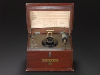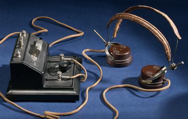
Sterling spark transmitter, No. 1 for airborne wireless, England, 1915. Almost identical to 1939-311 Sterling spark transmitter, No. 1, by W. D. Wireless Factory, Soho, London, England, 1914-1918 but lacking ammeter on top.
The Sterling tuned spark gap wireless transmitter operated on the frequency range of 100-260 metres. The transmitter's output of 30-40 Watts fed to the 120 feet of trailing aerial gave it an operating range of 8-10 miles. The set was usually mounted on a tray on the side of the aircraft fuselage. The trailing aerial of stranded copper wire with a 3Ib weight on the end was spooled out either from the side of aircraft fuselage alongside the wireless set or through an insulated gland in the floor.
The Sterling spark gap wireless transmitter, also referred to as the No. 1 Aircraft Transmitter Spark, was the first purpose-built airborne wireless set used by the Royal Flying Corps (RFC) in the First World War. It was first produced in late 1914 and brought into use in 1915. The transmitter and Morse key were totally enclosed to avoid a spark igniting the petrol vapour in the aircraft cockpit.
The wireless set was based on an initial design by Lieutenant Basil Binyon, RN, of the Royal Naval Air Service (RNAS) with advice from Captain Lefroy, both pioneers in airborne wireless communications. Around 1300 Sterling spark gap sets were made during the First World War, the first 100 or so by Sterling Telephone and Electric Company Limited at Tottenham Court Road, London and the remaining by War Department (W.D.) Factories.
The set was designed for airborne reconnaissance using Morse code, most commonly artillery spotting working with British Army artillery stations on the Western Front but also for spotting German U-boats at sea. Communication was in one direction only so the sender, usually the observer in a two-person biplane, had no way of knowing if the message had been received or not. Nonetheless, the set was very useful indeed with later examples having a transmitter and receiver. A later version, the Type 52, was introduced for the Royal Naval Air Service (RNAS) which operated on different frequency ranges. In April 1918, the RFC and RNAS merged to form the Royal Air Force (RAF).
Airborne wireless communications at the end of the First World War were completely transformed from the Sterling spark gap sets like this introduced early in the war. Early issues with electrical and sound interference from the aircraft had been solved by screen ignition leads; insulated flying helmets with headphones, mostly designed by S.G. Brown; and electrical amplifiers to improve signals.
But perhaps the most significant development was to the wireless sets themselves: first by improved tuning and later by the introduction of radio valves and radio telephony (voice communications). Additionally, aircraft were equipped with transmitters and receivers so two-way communication became possible. By the end of the First World War, some RAF fighter aircraft on the frontline were equipped with two-way voice communications via wireless using flying helmets with headphones and throat microphones capable of communication over distances of over 10 miles.
Details
- Category:
- Radio Communication
- Object Number:
- 1977-577
- Measurements:
-
overall: 185 mm x 215 mm x 150 mm,
- type:
- wireless transmitter
