Model of Bodmer's carding engine.
- Made:
- 1820-1824 in Manchester and United Kingdom
- patentee:
- John George Bodmer


![]() This image is released under a CC BY-NC-SA 4.0 Licence
This image is released under a CC BY-NC-SA 4.0 Licence
Buy this image as a print
BuyLicense this image for commercial use at Science and Society Picture Library
License![]() This image is released under a CC BY-NC-SA 4.0 Licence
This image is released under a CC BY-NC-SA 4.0 Licence
Buy this image as a print
BuyLicense this image for commercial use at Science and Society Picture Library
License![]() This image is released under a CC BY-NC-SA 4.0 Licence
This image is released under a CC BY-NC-SA 4.0 Licence
Buy this image as a print
BuyLicense this image for commercial use at Science and Society Picture Library
LicenseModel of two carding engines arranged so as to combine their
Science Museum Group
© The Board of Trustees of the Science Museum
Model of two carding engines arranged so as to combine their
Science Museum Group Collection
© The Board of Trustees of the Science Museum
Science Museum Group Collection
© The Board of Trustees of the Science Museum
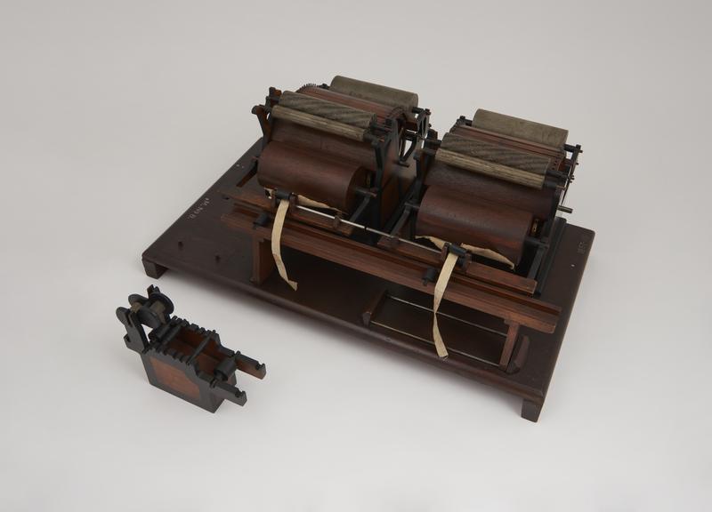
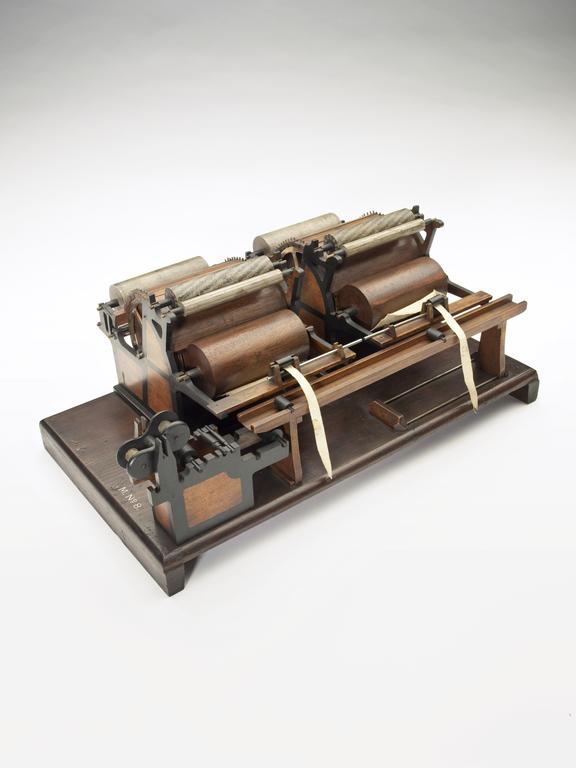
Model of two carding engines arranged so as to combine their slivers (scale 1:8), patentee John George Bodmer, unsigned, United Kingdom, 1820-1824
This is a model of an arrangement, included in J.G. Bodmer's patent of 1824, in which two carding engines preparing cotton to be spun into thread are placed side by side, and the slivers of cotton being fed into them are led through a trough and united into a single lap. Twenty or more carding engines could be combined in this way, the machines being arranged ten on each side of the trough, and the twenty slivers combined into a single lap. Bodmer's object in arranging so many carding engines together was to compensate for irregularities in the thickness of the sliver by averaging, but this result is obtained in modern practice by doubling in the finishing lap machine and in the drawing frame. The cotton has been previously opened, scutched, and formed into a lap. The lap is fed into the carding engine by rollers, and is carded in the usual way by wire cards or combs, carried upon the large main cylinder, the smaller rollers, and the top flats. The last are secured by pegs to the circumference of a ring concentric with the main cylinder, and there is an automatic arrangement, not shown in this model, however, which lifts the flats one by one and takes them to a revolving brush where they are cleaned, and then returns them to their working position.
Details
- Category:
- Textiles Machinery
- Object Number:
- 1857-115
- Materials:
- mahogany (wood), brass (copper, zinc alloy), steel (metal), brass and complete
- Measurements:
-
overall: 195 mm x 460 mm x 275 mm, 3.194kg
- type:
- model - representation
- credit:
- Bodmer, R.