model, scale 1:8, of compressed air power hammer
- Made:
- circa 1904 in Accrington
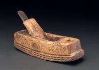
Model, scale 1:8, of compressed air power hammer, by Peter Pilkington Ltd, Bamber Bridge, Accrington
Power hammers were vital to engineering concerns working with wrought iron or steel, producing forgings on a variety of scales. Although many hammers were steam-powered along the lines established by Nasmyth or Massey, pneumatic hammers also came in to use, connected by air lines to a central compressor, air reservoir and accumulator. Such systems featured quite prominently in Pilkington's advertisements and frequent references in 'The Engineer' journal. and a number survive in different collections.
In this working model, the hammer-head is directly worked by an air cylinder, in which the pressure is being alternately diminished and increased by communication with another cylinder in which a piston is reciprocated by the motive power. By this system of working, which was first patented in 1860 by T. G. Dawes, an elastic, rapid and adjustable blow is obtained with a self-contained machine.
In the arrangement shown the hammer-head is directly connected with a plunger which serves as a single-acting piston and also as its guide, while the upper end of the cyli nder in which it works is in communication with another cylinder combined with the main standards and having in it a single-acting trunk piston actuated by a balanced crank on a flywheel shaft, driven by belting from line shafting or an electric motor.
The hammer is stopped or its blow varied by two rotary non-return slide valves in the passage connecting the two cylinders. One valve, actuated by a hand lever, controls the passage from the air cylinder to the valve chamber ; the other, which is connected with a treadle, controls the passage from the valve chamber to the hammer cylinder; at the top of the stroke the hammer piston passes over the port of this passage, so as to insure pneumatic cushioning.
When the passage is freer the motion of the hammer follows that of the air piston ; the force of the blow can, however, be lessened by slightly covering the port to the hammer cylinder. If the latter is completely covered, the hammer will be lifted to the top of its stroke and will remain there. If it is desired to retain the hammer in an intermediate position, the ports to both cylinders must be covered when that position is reached ; but if it is required to use the hammer as a vice, the port to the air cylinder must be covered and the port to the hammer cylinder uncovered. The air cylinder is provided with a safety non-return valve.
These hammers were built in sizes from I •5 to 10 cwt, that represented being of the smallest size, which had a stroke of 8 in and could deal with a maximum thickness of 2 in ; it gave 220 blows per minute and required 3 hp.
Details
- Category:
- Hand and Machine Tools
- Object Number:
- 1904-8
- Materials:
- cast iron, steel (metal) and paint
- type:
- models
- credit:
- Peter Pilkington Ltd.