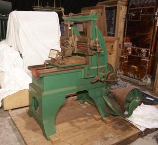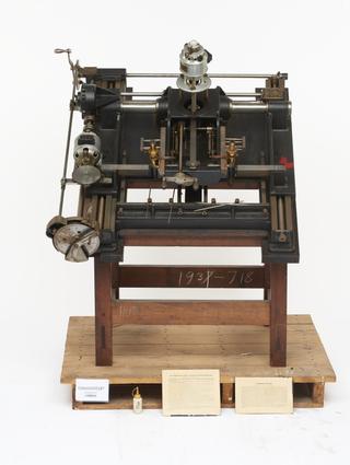
Cameograph carving machine
circa 1924
Cameograph carving machine, invented by H. Edmunds c1923 with examples of photo-sculpture and accessories.
This machine is one of a series, built for The Edmunds Cameograph Co, under patents of 1921 and 1923 taken out by H. M. Edmunds for the production of three dimensional figures from photographs.
The photographs are taken in a dark room, and the sitter is illuminated by a beam of light which has passed through a fine etched screen carrying a number of parallel lines. The two cameras are set to right and left-hand of the lantern so that the straight lines projected by the lantern, appear as contour lines on the photographic plates. The contour lines only are requisite for the later operations.
If the movements controlling the cutting tool in the machine are so arranged that lateral movement of the cross lines in a microscope, following the guide lines on the negative, can be translated into vertical changes in the position of the cutting tool, then the tool will reproduce the original subject to some selected scale.
The negatives are enlarged or diminished according to the size of carving desired, but the degree of relief obtained may be varied through a big range in the machining process itself.
The machine is in effect a vertical milling machine, with an automatic traverse and return, and a hand-feed controlled by the operator, who follows any given line on the plate through the microscope, by manipulating the hand feed; and as the microscope and cutter work in a definite but variable ratio to each other, the act of following the line alters the contour followed by the cutter, this continuing right across the plate. The same process is followed over every successive line, thus, in effect, turning the contour lines vertically through a 90 0 angle, and so reproducing the features of the sitter.
It will be realised that around certain features any given line may disappear from the view of one camera, but it is then visible to the other camera. As soon as the operator finds that a line has disappeared, he transfers his attention to the other microscope and carries on until it is again necessary to change.
Since the plates are right- and left-handed, the necessary correction in the right-hand microscope is in the reverse direction to that in the left. In order that the operator may not have to turn the feed the opposite way to attain apparently the same effect, so far as following the line is concerned, a reversing optical system is inserted in the right-hand microscope, whereby the mental process of following the line automatically is preserved. The feed lever on the left-hand side of the operator brings the reversing gear of the carriage into action, and at the same time advances the traverse to a pre-determined distance.
The degree of relief obtained from any given plate is varied by inserting different gear ratios in the cross shaft which engages with the vertical rack. An over-running safety device is provided at the rear of the machine. The machine will carve in many mediums, such as box-wood, ivory and alabaster, but the general method is to carve in a special plaster compound, the permanent plaques being cast there from in bronze.
circa 1924
1924-1931
1924-1931