Drawing of James Watt's Pumping Engine 1788
- maker:
- Science Museum

![]() This image is released under a CC BY-NC-SA 4.0
Licence
This image is released under a CC BY-NC-SA 4.0
Licence
License this image for commercial use at Science and Society Picture Library
License
Science Museum Group Collection
© The Board of Trustees of the Science Museum
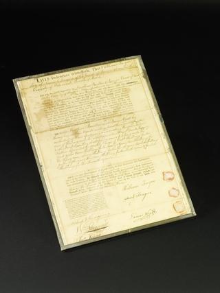
Drawing of James Watt's Pumping Engine, 1788.
This represents the arrangement supplied by Messrs. Boulton and Watt in 1788, but it differs only in detail from the standard Cornish pumping engine subsequently so extensively used. The engine valves are of the drop type, connected by racks and segmental arms with levers struck by tappets on the plug or air-pump rod; the top valve admits steam to the cylinder, and was known as the "expansion" valve, as it was set to cut off steam at about half-stroke, thereby allowing the remainder of the stroke to be performed by the expansion of the steam previously admitted without further demand upon the boiler. The lower or equilibrium valve is opened when the piston reaches the bottom of its stroke, thus allowing the steam above the piston to pass to the lower side, so that by the weight of the pump- rods the piston ascends to the upper end of the cylinder. The lowest valve controls the passage from the lower end of the cylinder to the condenser, and is open throughout the down-stroke of the piston. The well-known high economy of these engines is largely due to their acting somewhat as if compounded, since the upper portion of the piston and cylinder are never exposed to the low temperature of steam discharging into the con- denser; the cylinder also has a steam jacket. The closed top cylinder here employed was introduced by Watt in 1774. The boiler shown is of the "wagon" type, and probably worked at about 5 lb. per sq. in. above atmospheric pressure.
Details
Related Objects
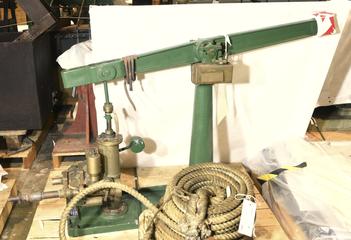
Hydraulic Organ Blowing Machine
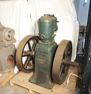
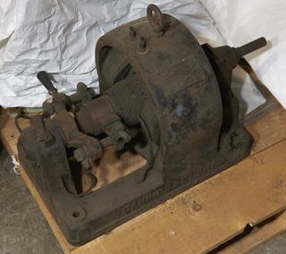
petrol engine
Frames containing prints of 1000 K.W. Ljungstrom steam turbine
Collotype, 6000 K.W. turbo-alternator