Model of Rotative Beam Engine by William Tongue, c. 1804

Model of Rotative Beam Engine by William Tongue, c. 1804 model, rotative beam engine, c model, rotative beam engine, c model, rotative beam engine, c model, rotative beam engine, c model, rotative beam engine, c model, rotative beam engine, c model, rotative beam engine, c

Creative Commons LicenseThis image is released under a CC BY-NC-SA 4.0 Licence

Buy this image as a print 

Buy

License this image for commercial use at Science and Society Picture Library

License

Creative Commons LicenseThis image is released under a CC BY-NC-SA 4.0 Licence

Buy this image as a print 

Buy

License this image for commercial use at Science and Society Picture Library

License

Creative Commons LicenseThis image is released under a CC BY-NC-SA 4.0 Licence

Buy this image as a print 

Buy

License this image for commercial use at Science and Society Picture Library

License

Creative Commons LicenseThis image is released under a CC BY-NC-SA 4.0 Licence

Buy this image as a print 

Buy

License this image for commercial use at Science and Society Picture Library

License

Creative Commons LicenseThis image is released under a CC BY-NC-SA 4.0 Licence

Buy this image as a print 

Buy

License this image for commercial use at Science and Society Picture Library

License

Creative Commons LicenseThis image is released under a CC BY-NC-SA 4.0 Licence

Buy this image as a print 

Buy

License this image for commercial use at Science and Society Picture Library

License

Creative Commons LicenseThis image is released under a CC BY-NC-SA 4.0 Licence

Buy this image as a print 

Buy

License this image for commercial use at Science and Society Picture Library

License

Creative Commons LicenseThis image is released under a CC BY-NC-SA 4.0 Licence

Buy this image as a print 

Buy

License this image for commercial use at Science and Society Picture Library

License

Science Museum Group Collection
© The Board of Trustees of the Science Museum

model, rotative beam engine, c
Science Museum Group Collection
© The Board of Trustees of the Science Museum

model, rotative beam engine, c
Science Museum Group Collection
© The Board of Trustees of the Science Museum

model, rotative beam engine, c
Science Museum Group Collection
© The Board of Trustees of the Science Museum

model, rotative beam engine, c
Science Museum Group Collection
© The Board of Trustees of the Science Museum

model, rotative beam engine, c
Science Museum Group Collection
© The Board of Trustees of the Science Museum

model, rotative beam engine, c
Science Museum Group Collection
© The Board of Trustees of the Science Museum

model, rotative beam engine, c
Science Museum Group Collection
© The Board of Trustees of the Science Museum

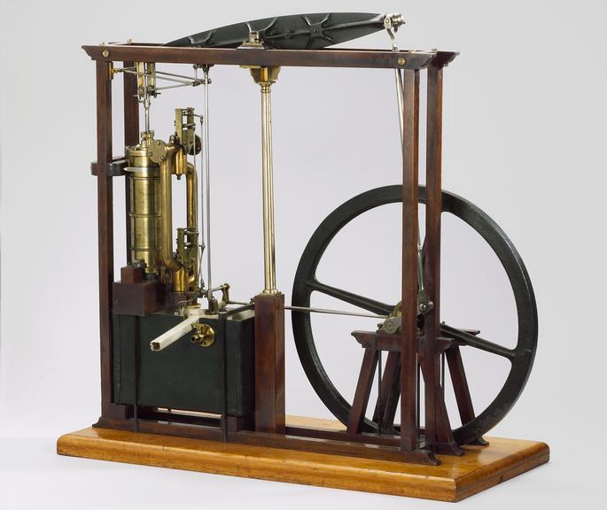
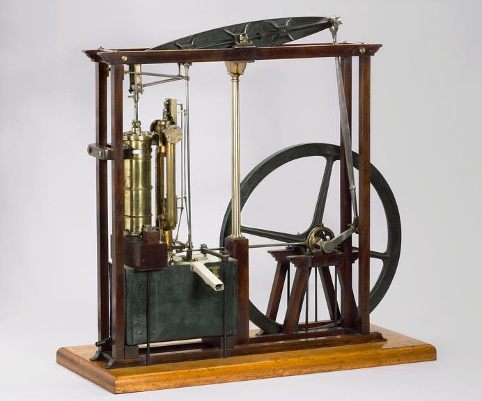
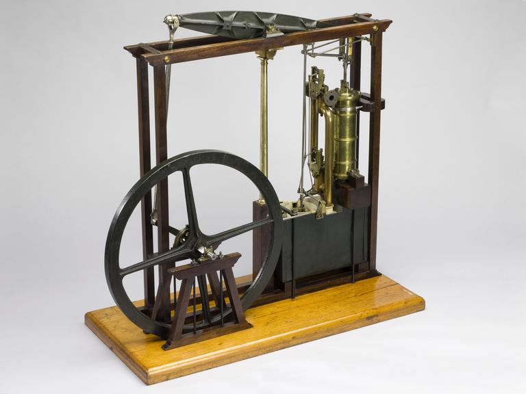
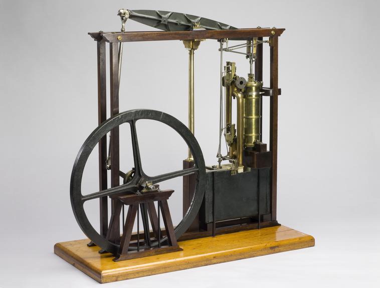
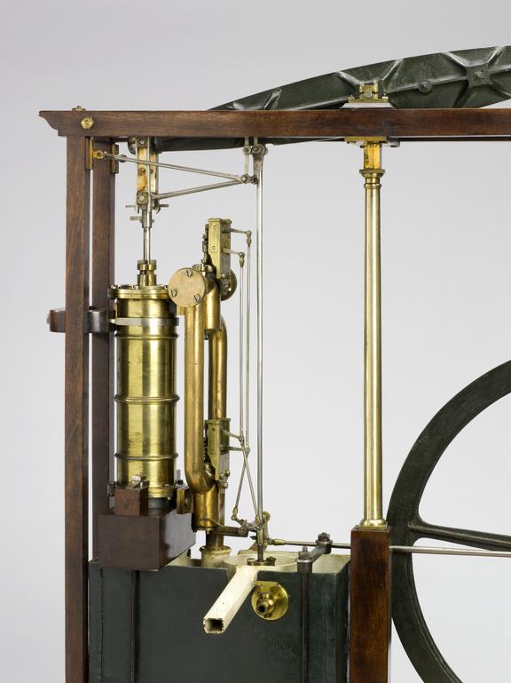
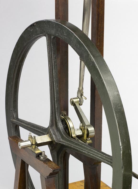
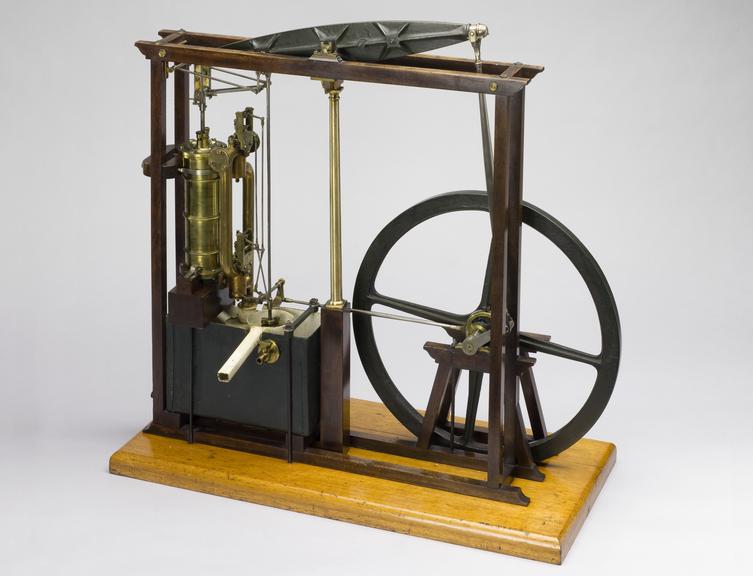
Model, rotative beam engine, c. 1805, scale 1:8, made by William Tongue, an apprentice with Boulton & Watt from 1797 until 1804. It represents the rotative steam engine as Watt left it upon the expiry of his patents in 1800. Cast iron has replaced timber in the main engine components, and the sun & planet gear has been replaced by a more straightforward crank. The nozzles (valve boxes that controlled the inlet and exhaust of steam at each end of the cylinder) each contain two concentric socket valves of the type introduced by William Murdock after 1800. The eccentric driving the valves was also his improvement.

This model was made by William Tongue, while an apprentice with Messrs. Boulton and Watt at Birmingham, 1797-1804 (see facsimile of the indenture of his apprenticeship, Inv. 1895-61). The general arrangement including the valve gear is similar to the model, inv. 1876-1254. The valves are of the tubular or "socket" type, introduced by William Murdock, rendering only one opening into each valve box necessary. The straight line motion of the air-pump rod is obtained from a pantograph extension of the main parallelogram as in No. 76. This was discarded for the simpler plan, which subsequently became general, of attaching the rod to the "parallel " point and looping the tie rod to clear it. The condenser is contained in a large rectangular tank situated under the cylinder. This tank also contains the air-pump which is provided with a cover carrying a stuffing-box through which the pump rod passes. The latter, by the friction of the packing, lifts the cover as far as permitted by three guiding stops, and is similarly lowered on the down stroke, an arrangement equivalent to a mechanically-moved delivery valve.

Details

Category:
Motive Power
Object Number:
1861-47
Materials:
ivory, steel (metal), mahogany (wood), complete, wood (unidentified), copper (metal), brass (copper, zinc alloy), iron and paint
Measurements:
overall (including mahogany stand): 800 mm x 800 mm x 370 mm, 27kg
type:
model, steam engine and rotative beam engine
credit:
Osman, M.H.