Drawing of Crown Cam Winding Gear
- maker:
- Science Museum
Drawing of Crown Cam Winding Gear, 1782 (Scale 1:36) From original drawings in the Boulton and Watt Collection at Birmingham
This is copied from an original drawing dated 1782 in the Boulton and Watt Collection at Birmingham, indicating that in all probability it was actually applied practically. It shows another of the mechanisms patented in 1781 by James Watt as an equivalent of the crank. A connecting rod from the engine beam rocks an equal-armed lever having two conical rollers mounted on it, one at either end. The centre on which the lever moves is close to a vertical shaft on which are mounted a crown cam of considerable throw and a heavy fly-wheel. By the reciprocation of the engine beam, the conical rollers are caused to press upwards alternately against the edge of the crown cam and through the inclined action cause it to rotate. The fly-wheel is for the purpose of carrying the cam over its dead centres. A spur pinion on the fly-wheel shaft gears into a large spur wheel formed on the winding drum.
Details
Related Objects
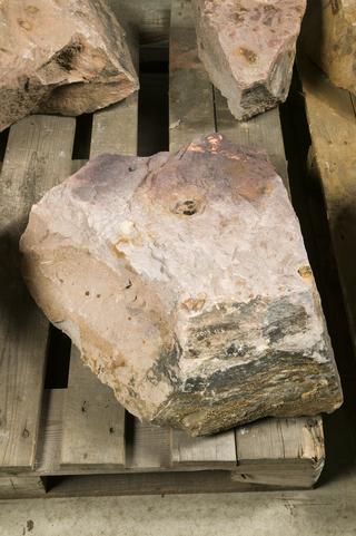
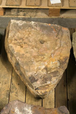
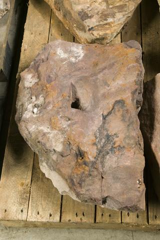
Sandstone Rock from Pollard Street Archaeological Excavations of Peel, Williams & Peel Co.'s Foundry
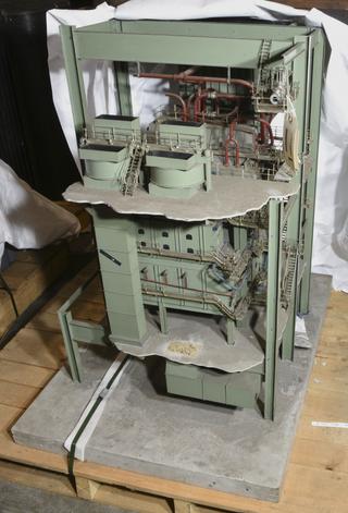
Model of Stirling Tri-drum Water Tube Boiler
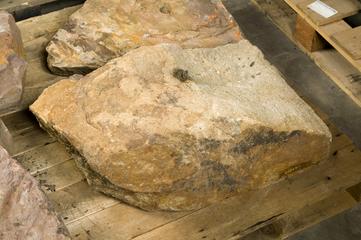
Sandstone Rock from Pollard Street Archaeological Excavations of Peel, Williams & Peel Co.'s Foundry
Sandstone Rock from Pollard Street Archaeological Excavations of Peel, Williams & Peel Co.'s Foundry