Parsons' turbine blade examples
- Made:
- circa 1909 in Heaton

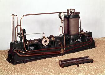
Examples illustrating Parsons turbine blading, rosary and comb types types, viz:- 7 blades 5 1/2 inches long; 7 roots for 5 1/2 inch. blades; 7 blades 3 inches long; 7 roots for 3 inch blades; 1 segment of 3 inch blading; 1 segment of 5 1/2 inch blading; 2 brass rods; 1 copper rod; 1 canvas board.
In the first Parsons turbine the blades were straight, and were milled out of solid rings, which were afterwards fitted to the spindle and casing. Later on they were still of uniform thickness and milled in solid rings, but their shape was improved by bending them. In 1896, however, the Hon. Sir Charles A. Parsons patented the present form of blade and the method of fixing them in plain or serrated grooves cut in the drum and casing. The blades are made of drawn brass and have indentations formed across their lower ends; they are cut to length and inserted in the grooves with correctly shaped distance pieces between them, which are then expanded by caulking tools so as to grip the blades and the sides of the grooves. One or more notches are cut in the edge of each long blade, and lacing strips are soldered into them so as to increase the rigidity of the blades. The tips are thinned down in the manner patented by the Hon. Sir Charles A. Parsons and Mr. G. G. Stoney in 1905, so that, should the blades touch the casing, the tips simply wear down. In this way radial clearance may be reduced to a minimum without danger of stripping. In order to assemble the turbines more rapidly, the blades, instead of being put in singly, are now made up into segments, consisting of a number of blades fastened together, and these are afterwards caulked into the grooves. Two methods of doing this are shown; in one, patented by the Hon. Sir Charles A. Parsons, Mr. G. G. Stoney, and Mr. D. F. Fullagar in 1899, and illustrated by a casing segment of 5.5 in. double-laced blades, the blades are set in notches milled along the side of a root strip, the metal between the notches being bent over so as to grip the blades, and the projecting corners afterwards levelled off; the whole is then bent to the required curvature. The grooves for this method have to be wider than the blades. The other, known as the rosary method, consists in threading the blades and distance pieces on a wire, and building them up on a former into complete segments with the lacing strips attached; this is shown by a rotor segment of in. blades with a single lacing strip. "" Specimens are also shown of separate 3 in. and 5.5 in. blades of the rosary type, together with their corresponding caulking sections and lacing_strips.
Details
- Category:
- Motive Power
- Object Number:
- 1909-6
- type:
- turbine blades
- credit:
- C A Parsons and Company Limited
