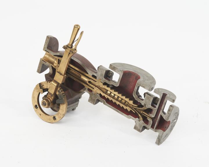
Ejector Condenser in section
- Made:
- 1882
 This image is released under a CC BY-NC-SA 4.0
Licence
This image is released under a CC BY-NC-SA 4.0
Licence
License this image for commercial use at Science and Society Picture Library
License
Science Museum Group
© The Board of Trustees of the Science Museum
Ejector Condenser in section patented by Korting Bros. in 1882
This apparatus, patented in 1882 by Mr. E. Korting, consists of a series of nozzles discharging into an expanding tube as in the ordinary injector, but a large number of drilled holes pointing in the direction of the flow permits of a further addition of steam to increase the velocity. An internal sliding tube, adjustable by a hand-lever, permits of the covering of these holes when starting, and of their being set in the position of maximum efficiency, as indicated by a vacuum gauge, when on regular work. The condensing or injection water enters at the top, and passing through the water nozzle has its velocity increased on entering the condensing tube, which is in the exhaust steam space, by the condensation in it of the steam. This velocity is further increased by the jets of steam entering through the inclined side holes. The condensed steam and the water rush downward to the outlet from which they can be carried to a cooling pond or elsewhere. At the top is a small nozzle by which a jet of live steam can be introduced at starting, so as to lift the injection water and prime the apparatus.
Details
- Category:
- Motive Power
- Object Number:
- 1893-204
- Measurements:
-
overall: 185 mm x 550 mm x 350 mm,
- type:
- condenser
- credit:
- Korting Bros.