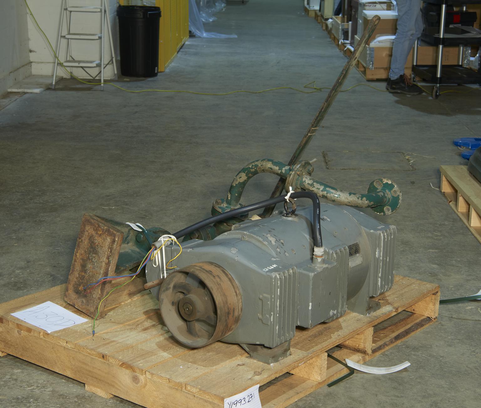
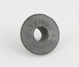
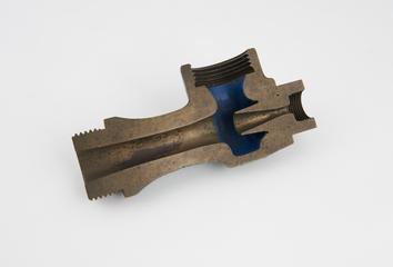
Hydraulic accumulator, made by Mather & Platt Ltd, Newton Heath, Manchester, 1907. Used at Shad Thames Pumping station in London.
Manchester’s hydraulic power network (1894-1972) had three pumping stations. Each pumping station had a set of pumping engines, which were connected to hydraulic accumulators that fed the hydraulic network. Each accumulator was basically a large cylinder – a piston – with an enormous weight on top. By pumping water into the piston, the weight could be raised to the top of the accumulator. This great weight pressing down kept the water in the network pressurised to 1000 lbs per square inch and ready to use.
Over 30 miles of thick pipes connected the power stations to customers. Users simply had to turn a tap to let high pressure water flow from the network to drive their machinery. As customers drew hydraulic power from the network, the giant weights in the power station accumulator fell, and more water had to be pumped in to maintain the pressure.


