Model mule headstock (scale 1:4)
- Object Number:
- 1871-31/1
- type:
- model
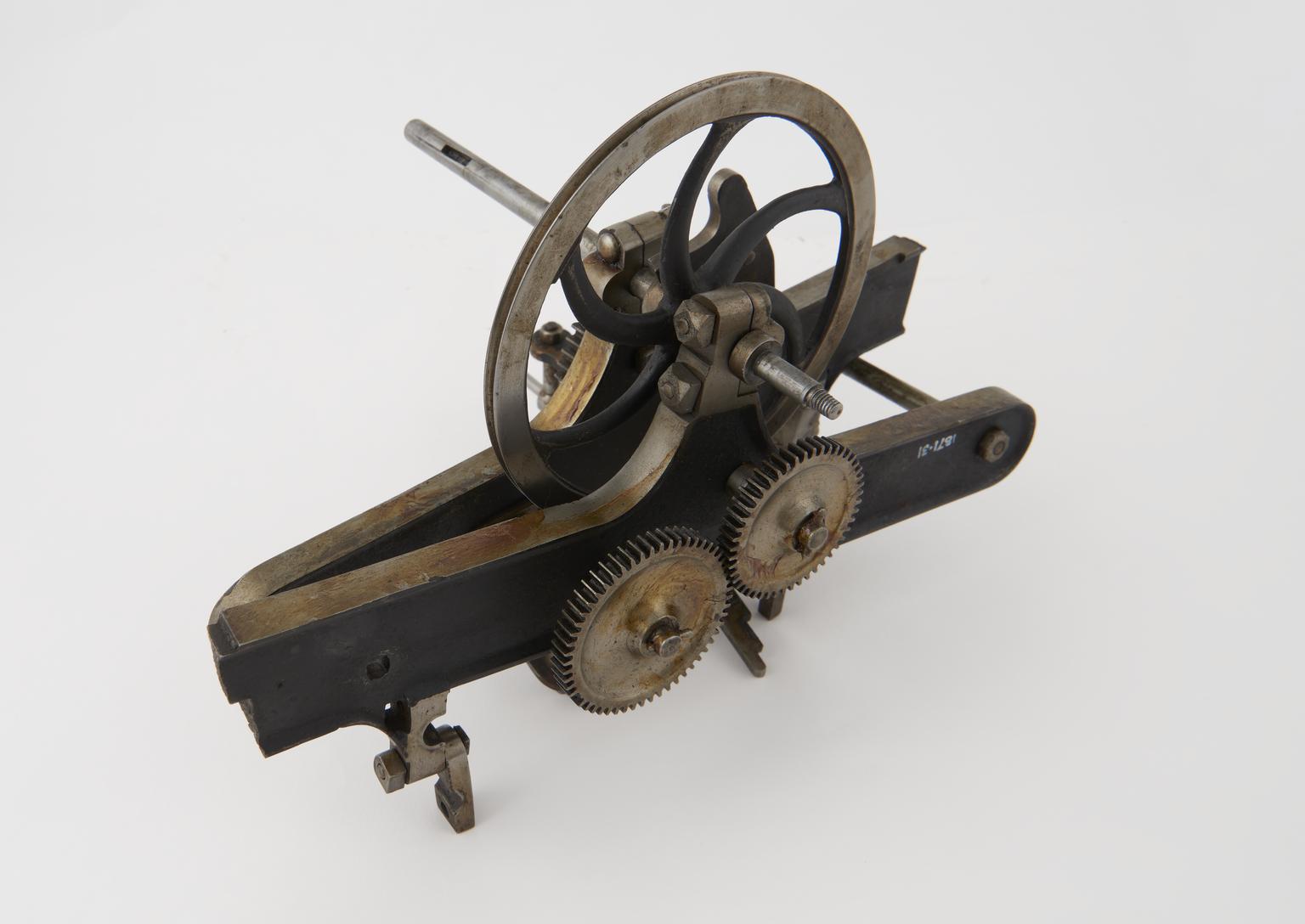
Model cotton-spinning mule headstock (scale 1:4), patentee James Potter.
This is a model of a headstock in which several of the mechanisms patented by James Potter in 1836 are introduced. Potter was a cotton spinner working in Manchester. The general mode of action of the mule to which this headstock belongs is similar to that of other spinning mules, and it is described in the adjacent model of a complete mule, No. 36. The distinctive features of the headstock are : the vertical arrangement with the intention of saving floor space; the use of a spiral drum and hyperbolic screw"for regulating the speed of the spindles while winding on; the employment of a revolving crank motion for taking in the carriage, and the use of a sector rack with a varying stop, for effecting the operation of backing off. The model is not complete, but shows the leading peculiarities of Potter's arrangements. The varying velocity of rotation required by the spindles, while winding on and building up the cop, is obtained from a conical spiral drum, made of sheet metal. Within it was to have been a nut, which could be screwed along axially, and that carried one end of the chain which, after passing round the drum, is connected with the spindle driving gear by the usual endless rope.' The drum is driven uniformly by bevel gearing during the winding-in of the carriage; and when forming the cop-bottom the drum chain is at the large end of the drum, so receiving its maximum motion with a moderate variation in velocity but, as the spindles fill, the drum chain is slowly advanced towards the other end of the drum, where the mean speed is less and the variations greater ; when the end is reached the nut ceases to travel, so that the cop, after this, is completed in a series of similar conical layers. The winding-on gear is driven through a clutch at the top of the headstock, and when this clutch is released the chain is unwound from the drum by a weight ready for the next winding on. For the backing-off motion this clutch is put into gear with a sector rack and cam, the varying amount of backing off required while building the cop being provided for by a vertical rod raised by a cam, so as to limit the motion of the rack. The motion of the carriage is given by a band on the pulley on the lowest shaft, which is reversed for the in-and-out movements. When the carriage is running in, this shaft is driven by a chain attached to an overhanging crank arm, which is slotted concentrically and rotated by a stud playing in the slot. When the crank has reached its highest position its weight causes it to swing round in advance of the stud, so leaving the carriage free to commence its outward motion, which is obtained from gearing connected with the drawing rollers.