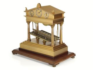
Rolling ball clock by E. Dent and Co
1920
Rolling ball clock by E. Dent & Co, London c.1920. The escapement is operated by a ball rolling down a zig-zag path cut in a plate pivoted at its centre and which tilts as the ball reaches the end of its travel. The movement is housed in a brass cover designed as a Greek temple with four Corinthian columns. There are three dials in the pediment for hours, minutes, and quarter minutes. Seconds are also indicated. Spring driven.

Model of mechanism for setting hands
Model by Dent of mechanism for setting hands and winding up a keyless watch

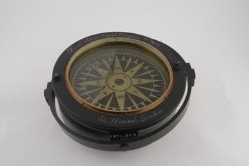
Dent's patent liquid compass with air chamber around rim
1860-1870
Dent's patent liquid compass with air chamber around rim, weighted with lead to improve stability, by E Dent and Company, London, 1860-1870

Model by Dent showing the mechanism of stop watches
Model by Dent showing the mechanism of stop watches (full size)
Marine balance springs
1875-1925
Marine balance springs
Model of a Lever Escapement , 1850-1883
1850-1883
Model by Dent of lever escapement for use with lantern, 1850-1883
Photograph of barometric compensation for new standard clock at the Royal Observatory
1876
Photograph (7"x9") of a barometric compensation for the new standard clock at the Royal Observatory, Greenwich, supplied and E. Dent & Co. Ltd., Strand, London, UNited Kingdom, 1876
Recording clock
1901-2000
Clock, recording clock (patent number 544119)
Copy of Gravesande's first heliostat
1878
Copy of Gravesande's first heliostat
Model representing Earnshaw's detent chronometer escapement, 1950-1883
1950-1883
Model of chronometer escapement, for use with a projecting latern, made by Dent, 1950-1883. Represents the detent chronometer escapement, invented by Thomas Earnshaw 1777-1787. This escapement was typically used in marine chronometers.
Model of Graham's Cylinder Escapement, 1850-1883
1850-1883
Model by Dent of Graham's cylinder escapement for use with lantern, 1850-1883
Recording clock
1901-2000
Clock, recording clock (patent number 544119)
Frame drawing of compensation pendulum
1876
Framed drawing (16½-inches x 2-foot 6-inches) of a compensation pendulum.