Model of a traction engine
- Made:
- 1859-1862


Traction engine, model, (scale 1:12)
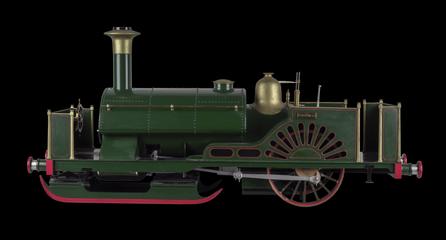
This model illustrates the traction engine patented by Messrs. R. Longstaff and A. Pullan in 1859. Its chief feature was that the cylinders and driving gear were mounted on a frame independent of the boiler.
The engine had a main frame composed of inner and outer members, the front end being mounted on a two-wheeled pivoted forecarriage, fitted with semi-elliptic springs, while the rear end was hung by links and springs from the ends of the driving wheel axles. The boiler had its smokebox end supported by levers connected with a handwheel and screw by which it could be raised or lowered to keep the boiler level on inclines.
On each side of the boiler was a vertical frame carrying one cylinder and bearings for the crankshaft, countershaft, and driving wheel axle. The front ends of these frames were mounted on the transverse shaft, while their rear ends were connected by a rigid crossframe behind the firebox. The crankshaft had overhung cranks at its ends, set at right angles, and on it were fixed two spur wheels of different diameters. The countershaft carried, between its bearings, two corresponding spur wheels, wither of which could be moved endwise by a screwed sleeve to engage with one of the wheels of the crankshaft, so that two driving speeds were available. The ends of the countershaft carried two slideable pinions which engaged with toothed rings bolted to the driving wheel spokes.
The driving wheels had bent wrought-iron spokes set in cast iron naves, the rims being of wood with iron tyres. In order to increase the bearing surface on the road, when necessary, additional smaller wheels were placed beside the main wheels and were driven from them by side cogs on the wheel rims. These wheels were mounted on eccentrics on a cross-shaft, so that they could be raised or lowered when that shaft was rotated by a wormwheel and screw.
The forecarriage was steered by a man seated on a front platform and turning a large vertical wheel. This wheel drove, by a pitch chain, two short shafts mounted below the main frame and having attached to them, by universal joints, right and left-handed screws passing through nuts pivotally attached to the forecarriage.
The cylinders were 8 inches in diameter by 15 inches in stroke, the driving wheels being 8.8 ft diameter and 8 inches wide. The leading wheels were 52 inches in diameter and the wheelbase was 10.75 feet.
Details
- Category:
- Road Transport
- Object Number:
- 1862-14
- type:
- traction engine and model
- credit:
- Gardner and Mackintosh
