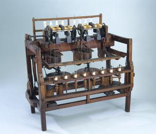
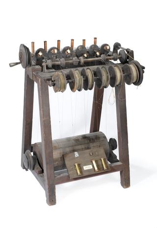
Arkwright's original drawing frame (lantern frame), 1775.
1775-1785
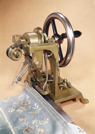
Arkwright's drawing frame, commonly known as a lantern frame, and fragments from the original wooden pulley, England, 1775-1785
Richard Arkwright is indelibly associated with the changes in production that came to be known as the Industrial Revolution. His particular talent was for exploiting innovation rather than actual invention and his machines all had origins in earlier efforts by others.
Arkwright’s lasting monument is the factory (or mill, as it was known in the textile industry). This concept arose from his appreciation that the manufacture of cotton yarn was a series of operations which could be undertaken in sequence by a suite of special purpose machines, gathered together in a single place and driven by a single power source.
Before Arkwright’s innovations most textiles were made in the homes of the spinners and weavers and the production of cotton was low, relative to wool and linen. After Arkwright, production became centralised in factories, designed to make efficient use of a range of machines, and to allow the management of labour.
The Arkwright system helped to establish Britain’s position in the nineteenth century as the world leader in textile production, but it also had wider international effects. British machine spinning led to the destruction of the Indian cotton spinning industry, while demand for raw cotton sustained the slave economy in the USA.
Specifically regarding the machine itself, this is Sir Richard Arkwright's first drawing frame, and was made by him about 1780. It was commonly known as the lantern frame, owing to the fact that the sliver-can employed had an opening in the side closed by a door through which the sliver was removed, and so somewhat resembled a lantern. In this machine the front rollers turn at three times the speed of the back pair, and the sliver is fed on from the back of the machine through a fork which travels to and fro continuously, guiding the sliver to different parts of the rollers. It receives its reciprocating motion from a crank pin on a pulley, turned by bands from the main driving drum, the axis of which is vertical. After passing through the drawing rollers the sliver is led down through a short tube to a pair of rollers attached to the top of a vertical can of conical shape. The can is driven by a band from the main drum, and on its axis is fixed a pulley, from which a band passes over guide pulleys to the pair of rollers on the can, so that they feed the cotton into the can at a definite speed, while the turning of the can puts into the sliver a slight twist.