model of slot or cotter-hole drilling machine
- Made:
- 1857 in Manchester
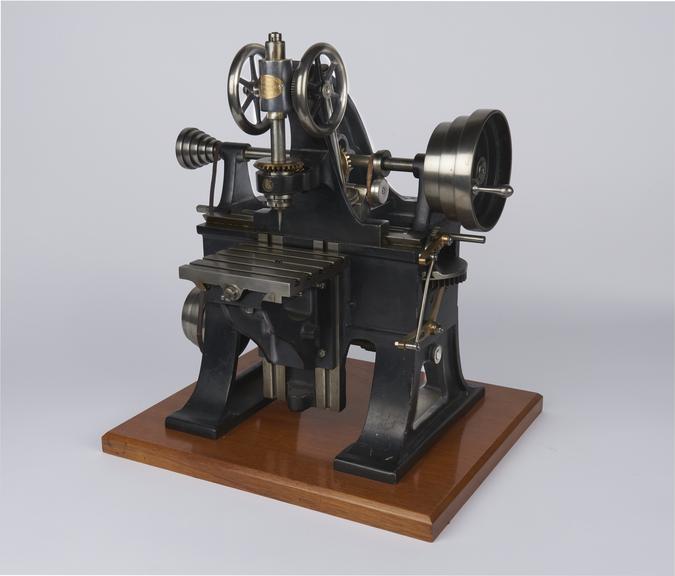
Model of slot or cotter-hole drilling machine, scale 1:4, by Sharp Stewart & Co, Atlas Works, Manchester, 1857
This machine was patented by T. B. Sharp and R. Furnival for cutting elongated holes by means of a revolving tool, somewhat resembling a drill, slowly travelling to and fro over the length of the required slot.
The machine has a box bed supported on standards with an adjustable table projecting in front to carry the work, which remains stationary during the operation. The overhanging drill headstock slides along the top of the bed and the rotary motion is transmitted to the tool by gearing from a longitudinal feather shaft. The longitudinal reciprocating motion of the headstock is obtained from an adjustable horizontal crank and connecting rod, which drive a screwed spindle passing through a nut on the underside of the head, so that both the length and position of the slot can be adjusted. The crank motion is worked from a countershaft below the bed, driven by a belt from the upper shaft, which drives the crank by worm gear and an eccentric pinion gearing with an elliptical wheel on the crank disc. In this way the angular velocity of the crank is varied so as to render the traversing motion of the drill fairly uniform. The intermittent vertical feed motion to the drill is transmitted through a friction clutch and worm gear from a ratchet wheel actuated by a cam on the crank disc. When the clutch is released the drill can be raised or lowered by hand. A continuous vertical feed, used for ordinary drilling, is provided by worm gear through another clutch driven by a belt from the upper shaft.
Details
- Category:
- Hand and Machine Tools
- Object Number:
- 1868-21
- Materials:
- cast iron, steel (metal), wrought iron and gunmetal
- type:
- models
- credit:
- Institution of Civil Engineers
