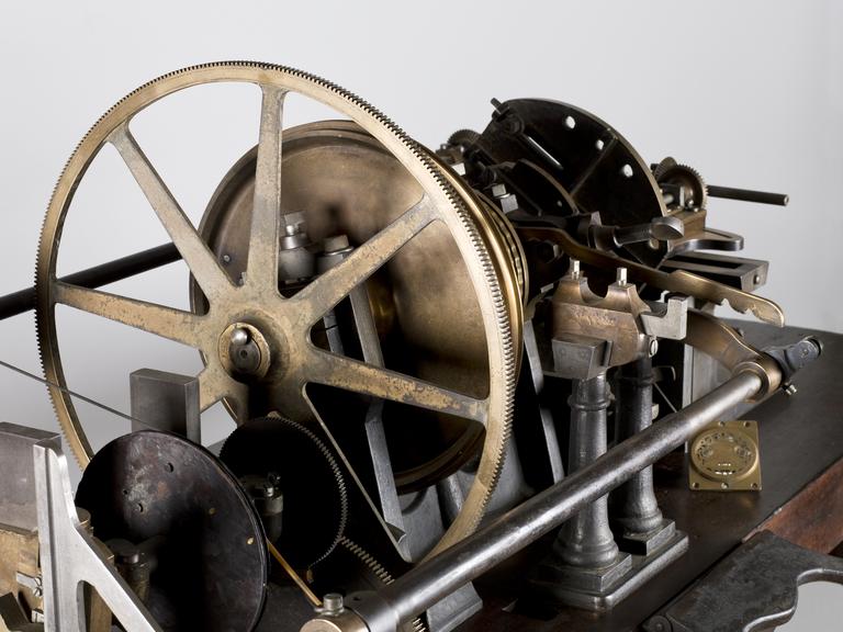
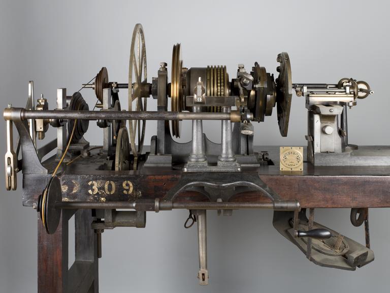
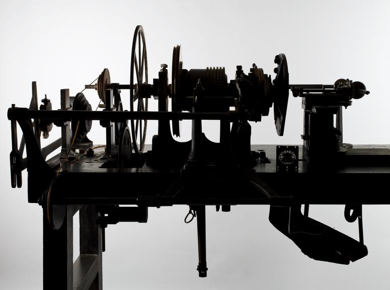
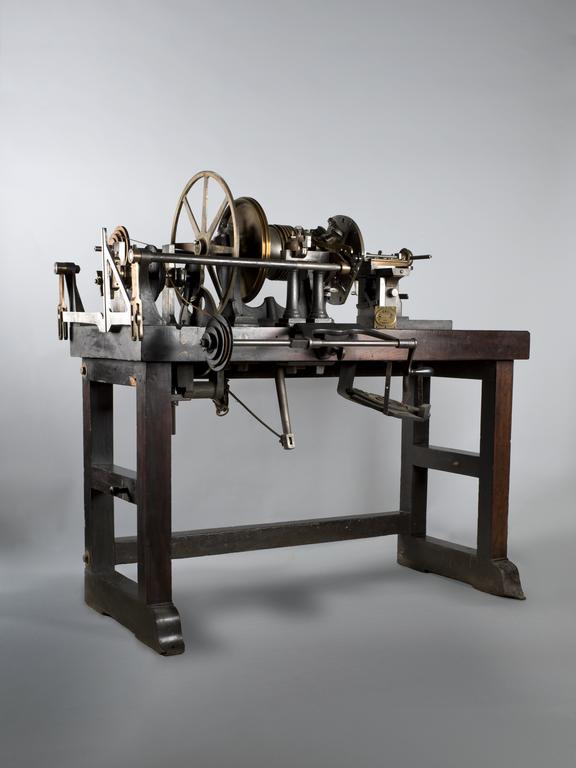
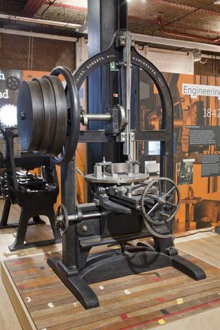
Rose engine lathe used to manufacture compound printing plates, built by Bryan Donkin, London, 1821.

Made:
1821 in London
Rose engine lathe used to manufacture compound printing plates Rose engine lathe used to manufacture compound printing plates Rose engine lathe used to manufacture compound printing plates, built by Bryan Donkin, London, 1821. Rose engine lathe used to manufacture compound printing plates, built by Bryan Donkin, London, 1821. Rose engine lathe used to manufacture compound printing plates Rose engine lathe used to manufacture compound printing plates, built by Bryan Donkin, London, 1821. Rose engine lathe used to manufacture compound printing plates, built by Bryan Donkin, London, 1821. Rose engine lathe used to manufacture compound printing plates, built by Bryan Donkin, London, 1821. Rose engine lathe used to manufacture compound printing plates Rose engine lathe used to manufacture compound printing plates Rose engine lathe used to manufacture compound printing plates, built by Bryan Donkin, London, 1821. Rose engine lathe used to manufacture compound printing plates, built by Bryan Donkin, London, 1821.

Creative Commons LicenseThis image is released under a CC BY-NC-SA 4.0 Licence

Buy this image as a print 

Buy

License this image for commercial use at Science and Society Picture Library

License

Creative Commons LicenseThis image is released under a CC BY-NC-SA 4.0 Licence

Buy this image as a print 

Buy

License this image for commercial use at Science and Society Picture Library

License

Creative Commons LicenseThis image is released under a CC BY-NC-SA 4.0 Licence

Buy this image as a print 

Buy

License this image for commercial use at Science and Society Picture Library

License

Creative Commons LicenseThis image is released under a CC BY-NC-SA 4.0 Licence

Buy this image as a print 

Buy

License this image for commercial use at Science and Society Picture Library

License

Creative Commons LicenseThis image is released under a CC BY-NC-SA 4.0 Licence

Buy this image as a print 

Buy

License this image for commercial use at Science and Society Picture Library

License

Creative Commons LicenseThis image is released under a CC BY-NC-SA 4.0 Licence

Buy this image as a print 

Buy

License this image for commercial use at Science and Society Picture Library

License

Creative Commons LicenseThis image is released under a CC BY-NC-SA 4.0 Licence

Buy this image as a print 

Buy

License this image for commercial use at Science and Society Picture Library

License

Creative Commons LicenseThis image is released under a CC BY-NC-SA 4.0 Licence

Buy this image as a print 

Buy

License this image for commercial use at Science and Society Picture Library

License

Creative Commons LicenseThis image is released under a CC BY-NC-SA 4.0 Licence

Buy this image as a print 

Buy

License this image for commercial use at Science and Society Picture Library

License

Creative Commons LicenseThis image is released under a CC BY-NC-SA 4.0 Licence

Buy this image as a print 

Buy

License this image for commercial use at Science and Society Picture Library

License

Creative Commons LicenseThis image is released under a CC BY-NC-SA 4.0 Licence

Buy this image as a print 

Buy

License this image for commercial use at Science and Society Picture Library

License

Creative Commons LicenseThis image is released under a CC BY-NC-SA 4.0 Licence

Buy this image as a print 

Buy

License this image for commercial use at Science and Society Picture Library

License

Rose engine lathe used to manufacture compound printing plates
Science Museum Group Collection
© The Board of Trustees of the Science Museum

Rose engine lathe used to manufacture compound printing plates
Science Museum Group Collection
© The Board of Trustees of the Science Museum

Science Museum Group Collection
© The Board of Trustees of the Science Museum

Science Museum Group Collection
© The Board of Trustees of the Science Museum

Rose engine lathe used to manufacture compound printing plates
Science Museum Group Collection
© The Board of Trustees of the Science Museum

Science Museum Group Collection
© The Board of Trustees of the Science Museum

Science Museum Group Collection
© The Board of Trustees of the Science Museum

Science Museum Group Collection
© The Board of Trustees of the Science Museum

Rose engine lathe used to manufacture compound printing plates
Science Museum Group Collection
© The Board of Trustees of the Science Museum

Rose engine lathe used to manufacture compound printing plates
Science Museum Group Collection
© The Board of Trustees of the Science Museum

Science Museum Group Collection
© The Board of Trustees of the Science Museum

Science Museum Group Collection
© The Board of Trustees of the Science Museum

Rose engine lathe used to manufacture compound printing plates, built by Bryan Donkin, Bermondsey, London, 1820.

Sir William Congreve patented a process known as compound-plate printing in 1821, and the printing plates were engraved using this machine. It was devised primarily as a means of preventing forgery – from 1797 until 1821 Britain depended solely on paper currency, and in the decade to 1820 detected counterfeiting cases rose by more than 500%. Compound printing became widely used for producing duty stamps, postage stamps and much else from the 1820s onwards - but not for manufacturing banknotes, where a combination of techniques which also included compound printing, were applied.

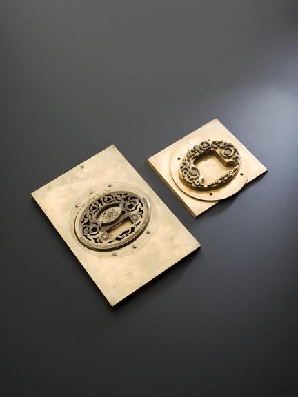
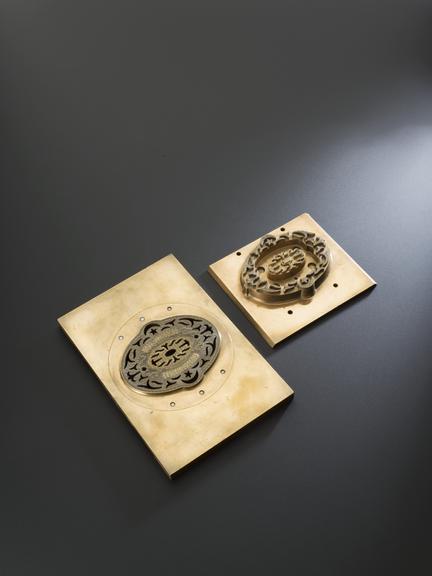
Congreve’s concept was completely new, and he gave the practical project of making it work to Bryan Donkin. The process consists of highly detailed two-colour printing. This was done using a printing plate comprising two intricate and interlocking parts, an upper part fitting through appropriately-shaped apertures in the lower part. The two parts were separated vertically so that two different colour inks could be applied (one to each) and then they were brought together and the impression made on paper. Most importantly, the detail engraved on the two-part plate was made while they were fitted together, so any potential forgers were faced with the near-impossible challenge of not only reproducing the complex mathematical shapes generated by the machine, but also duplicating the colour changes for each individual line exactly.

Unlike other ornamental lathes, the lathe has neither tail stock nor moving carriage, the small amount of necessary longitudinal movement being achieved from a compound slide mounted on the cross slide. The main spindle carries a gang of only five rose cams, which were used merely for outline patterns. The more usual way of producing wave patterns on this lathe is to disconnect the rubber from the roses and connect in its place a rocking lever system: mounted on the main spindle beyond the roses and drive pulley is a 360—toothed spur gear which, through an open gear train, rotates an adjustable cam (or eccentric) situated at the far left hand corner of the lathe. This in turn rocks a lever system, which is connected back to the main spindle.

Both the eccentric cam and the cross slide have fine adjustment screws and measuring scales with which to vary the depth of the wave, whilst change wheels give gear ratios to generate any number of waves from four to sixty per revolution. Another strange (if not unique) feature of the lathe is a bevel drive from the rear of the machine which, when engaged, rotates the engraving tool holder, the resulting circular path of the tool tip being varied by a tiny counterslide.

Details

Category:
Hand and Machine Tools
Object Number:
2008-26
Materials:
mahogany (wood), wrought iron, cast iron, gunmetal and paint
type:
rose engine
credit:
Bryan Donkin Archive Trust

Parts

Rose engine lathe used to manufacture compound printing plates, built by Bryan Donkin, London, 1821.

Rose engine lathe used to manufacture compound printing plates, built by Bryan Donkin, London, 1821.

Rose engine lathe used to manufacture compound printing plates, built by Bryan Donkin, Bermondsey, London, 1820.

Rose engine lathe component

Rose engine lathe component

Rose engine lathe component

Object Number:
2008-26/1/2
type:
component, rose engine
Image ©
The Board of Trustees of the Science Museum
Part of:
2008-26/1
Plaque

Plaque

Plaque - ImechE Engineering Heritage award

Object Number:
2008-26/2
type:
plaque

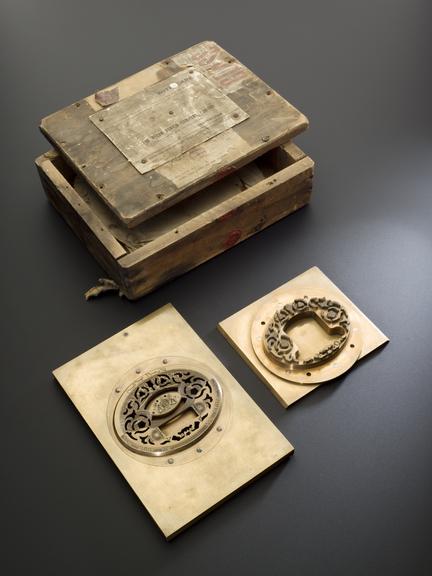
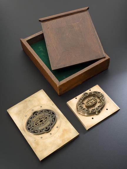
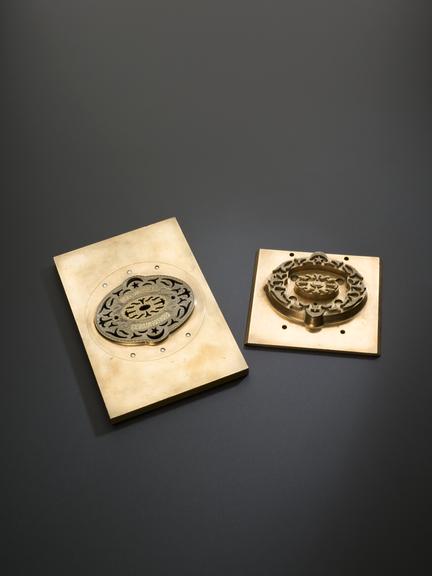
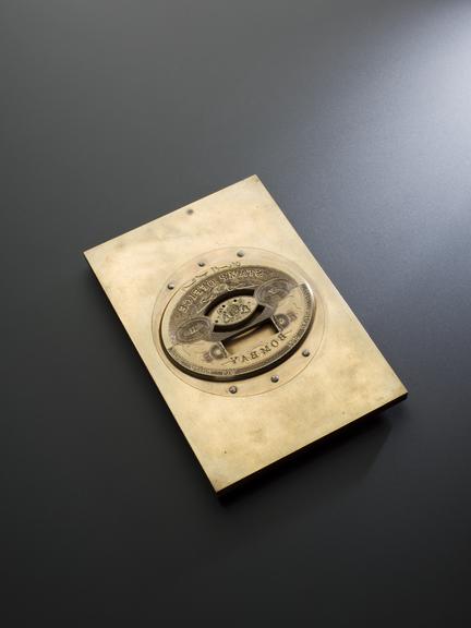
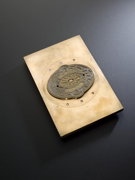
Two Indian revenue stamp dies, with mahogany case

Large die for printing Indian revenue stamps, c. 1872

Materials:
metal (unknown) and mahogany (wood)
Object Number:
2008-26/3
type:
die
Image ©
The Board of Trustees of the Science Museum

Large unfinished die in wooden box

Large unfinished die ('pattern plate') for printing Indian revenue stamps, in wooden box with label: BOMBAY STAMP OFFICE, 1868

Object Number:
2008-26/4
type:
die and box - container
Image ©
The Board of Trustees of the Science Museum
Large unfinished die for printing Indian stamps

Large unfinished die for printing Indian stamps

Large unfinished die ('pattern plate') for printing Indian revenue stamps.

Materials:
metal (unknown)
Object Number:
2008-26/4/1
type:
die
Part of:
2008-26/4
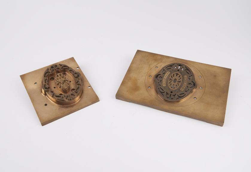
Die for printing Indian revenue stamps

Die for printing Indian revenue stamps

Small die (unfinished) for printing Indian revenue stamps, c. 1870 (on rose engine)

Materials:
metal (unknown)
Object Number:
2008-26/5
type:
die
Image ©
The Board of Trustees of the Science Museum
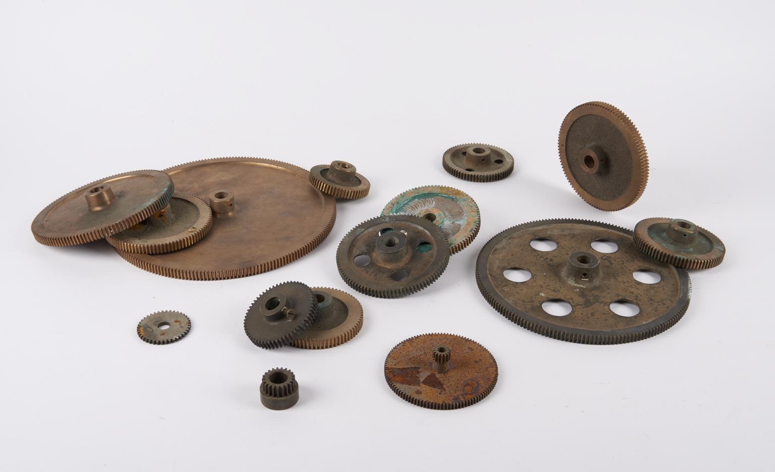
Box of gears for rose engine

Box of gears for rose engine

Box of gears for rose engine, seven original, eight new

Materials:
metal (unknown)
Object Number:
2008-26/6
type:
gears
Image ©
The Board of Trustees of the Science Museum
Top part of bellows, from rose engine

Top part of bellows, from rose engine

Top part of bellows (on rose engine)

Object Number:
2008-26/7
type:
bellows
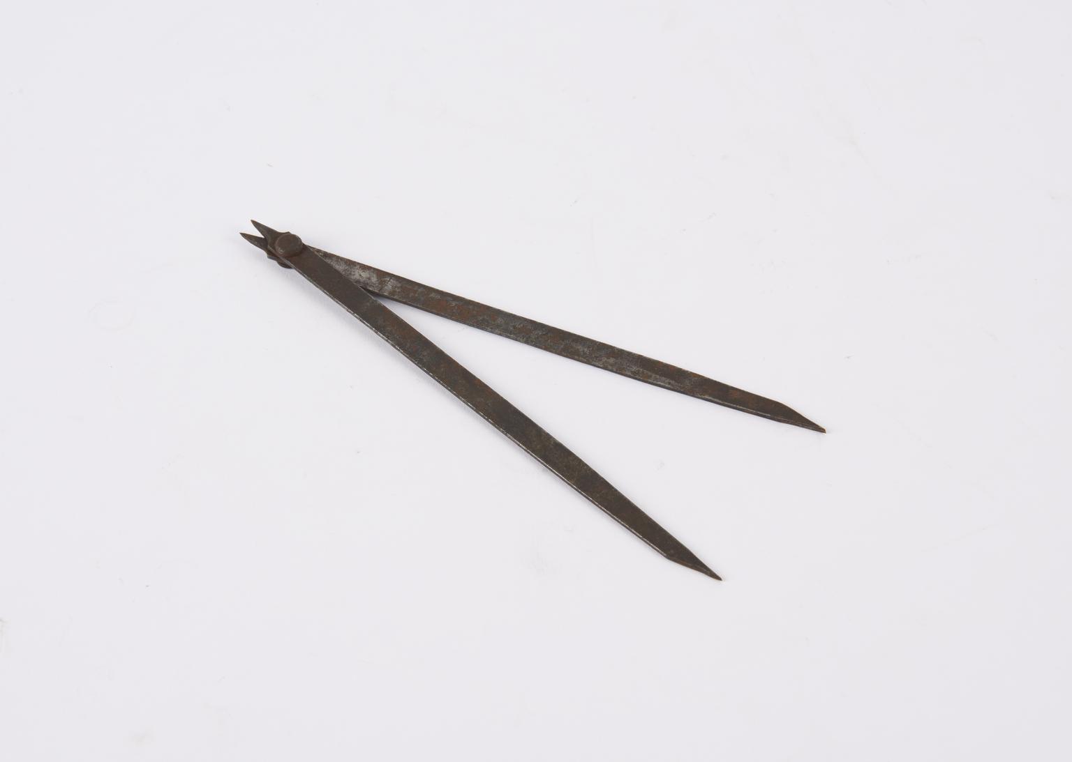
Double-ended dividers used with Rose Engine Lathe Machine

Double-ended dividers used with Rose Engine Lathe Machine

Double-ended dividers (1:4)

Materials:
metal (unknown)
Object Number:
2008-26/8
type:
dividers
Image ©
The Board of Trustees of the Science Museum
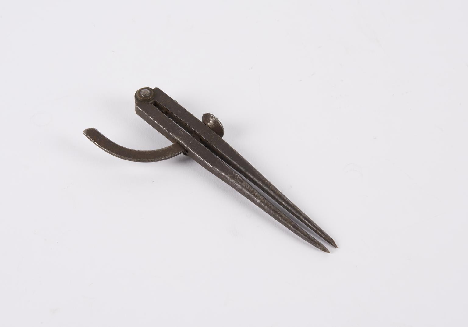
Dividers with setting screw

Dividers with setting screw

Dividers with setting screw

Materials:
metal (unknown)
Object Number:
2008-26/9
type:
dividers
Image ©
The Board of Trustees of the Science Museum
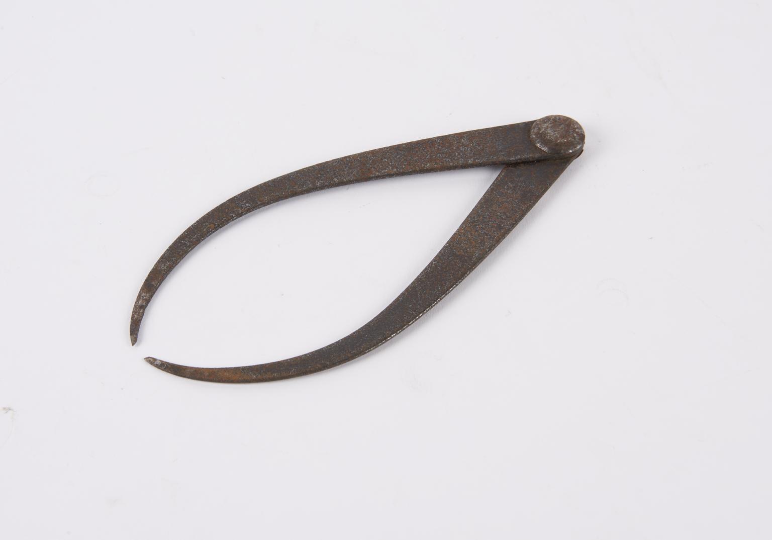
Outside callipers

Outside callipers

Outside callipers

Materials:
metal (unknown)
Object Number:
2008-26/10
type:
callipers
Image ©
The Board of Trustees of the Science Museum
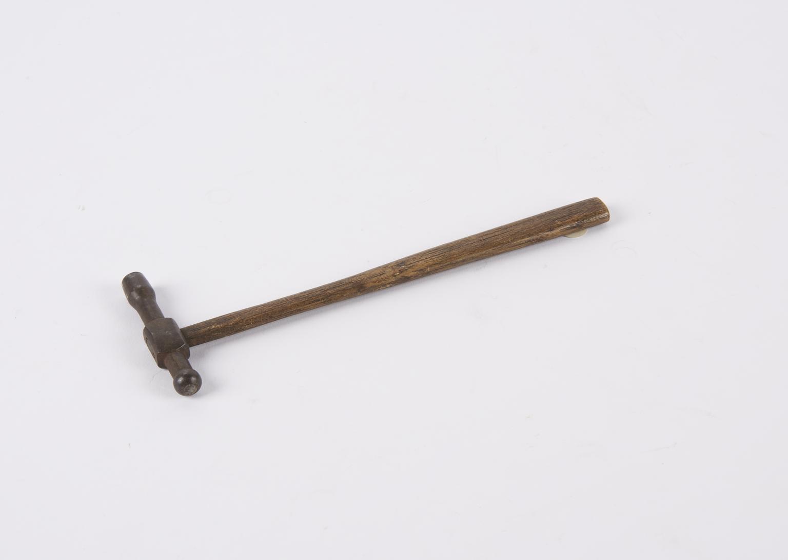
Small hammer

Small hammer

Small hammer

Materials:
metal (unknown)
Object Number:
2008-26/11
type:
hammer
Image ©
The Board of Trustees of the Science Museum
Tool slide for rose engine

Tool slide for rose engine

Tool slide for rose engine

Materials:
metal (unknown)
Object Number:
2008-26/12
type:
tool slide
Handle for rose engine

Handle for rose engine

Handle for rose engine (on rose engine)

Object Number:
2008-26/14
type:
handle
Handle for chuck jaws

Handle for chuck jaws

Handle for chuck jaws

Object Number:
2008-26/15
type:
handle
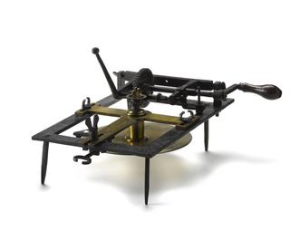
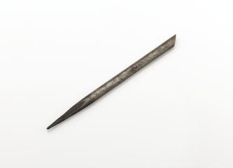
Bellows pipe

Bellows pipe

Bellows pipe. Marked with '+GF+ 1/8'.
Object Number:
2008-26/16
type:
bellows pipe
5 screws for tool slide from rose engine lathe

5 screws for tool slide from rose engine lathe

Five spare screws for tool slide

Object Number:
2008-26/17
type:
screws
Jig for turning/engraving movables

Jig for turning/engraving movables

Jig for turning/engraving movables

Object Number:
2008-26/18
type:
jig
Metal shield

Metal shield

Metal shield

Object Number:
2008-26/19
type:
metal shield
Rectangular jig

Rectangular jig

Rectangular jig with applied shapes

Object Number:
2008-26/20
type:
jig
Jig for turning movables

Jig for turning movables

Jig for turning movables

Object Number:
2008-26/21
type:
jig
Change wheel from the rose engine lathe

Change wheel from the rose engine lathe

Change wheel

Object Number:
2008-26/22
type:
change wheel
20lb weight

20lb weight

20lb weight

Object Number:
2008-26/23
type:
weight
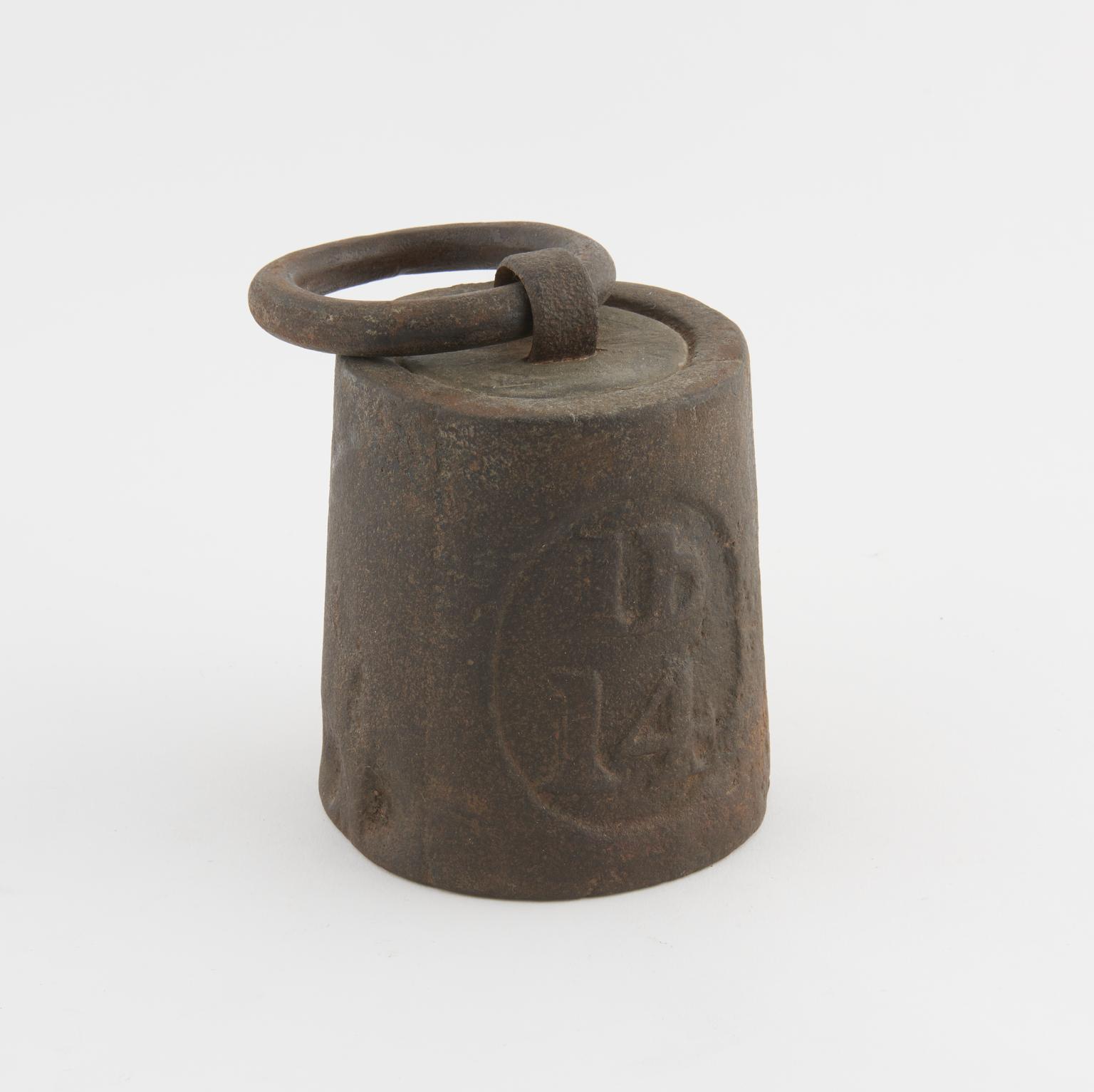
Two 14lb weights

Two 14lb weights

2 off 14lb weights

Object Number:
2008-26/24
type:
weights
Image ©
The Board of Trustees of the Science Museum
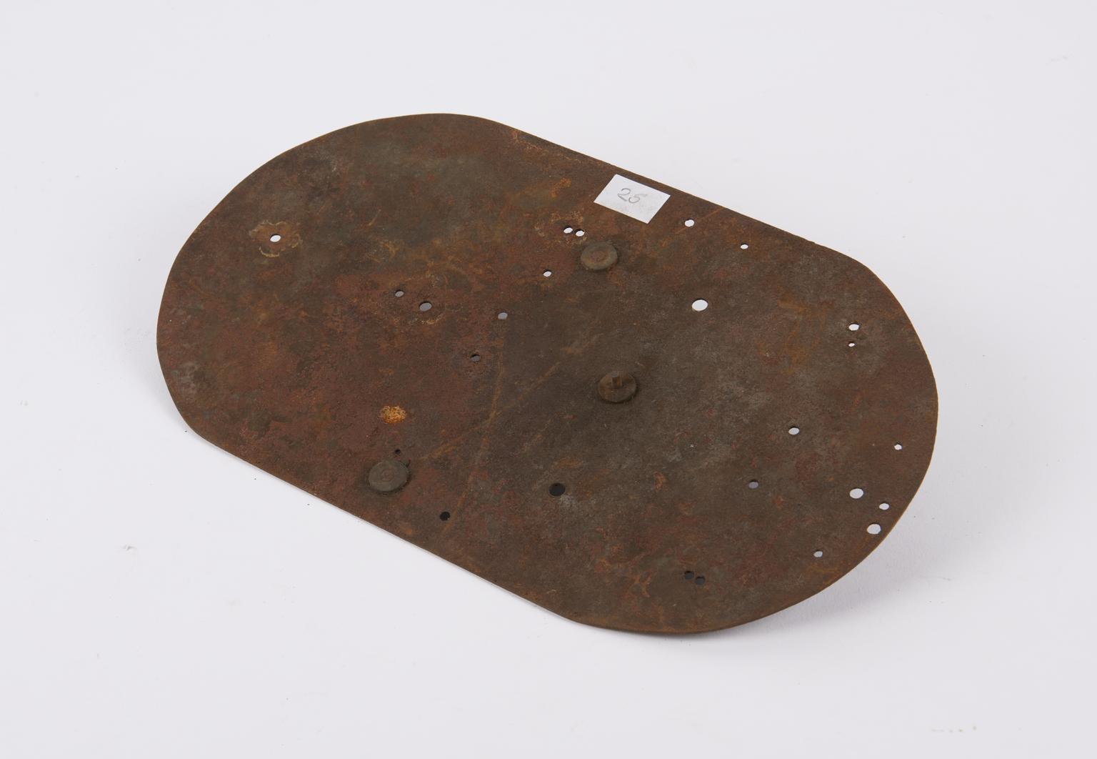
Metal oval with stud on base

Metal oval with stud on base

Metal oval with stud on base

Materials:
metal (unknown)
Object Number:
2008-26/25
type:
oval
Image ©
The Board of Trustees of the Science Museum
Oil can

Oil can

Oil can

Object Number:
2008-26/26
type:
oil can
Rectangular brass jig

Rectangular brass jig

Rectangular brass jig for cutting and engraving finished die

Object Number:
2008-26/27
type:
jig - tool
Circular metal jig

Circular metal jig

Circular metal jig for machining movables

Object Number:
2008-26/28
type:
jig
Multipurpose metal jig

Multipurpose metal jig

Multipurpose rectangular metal jig

Object Number:
2008-26/29
type:
jig - tool
Bakelite fixture for holding ovals

Bakelite fixture for holding ovals

Rectangular Bakelite fixture for holding ovals

Object Number:
2008-26/30
type:
bakelite fixture
Display panel with five photos showing removal and cleaning of rose engine

Display panel with five photos showing removal and cleaning of rose engine

Display panel with five photos showing removal and cleaning of rose engine

Object Number:
2008-26/31
type:
panel
Display panel with three photos and spectrograph showing restoration of rose engine

Display panel with three photos and spectrograph showing restoration of rose engine

Display panel with three photos and spectrograph showing restoration of rose engine

Object Number:
2008-26/32
type:
panel
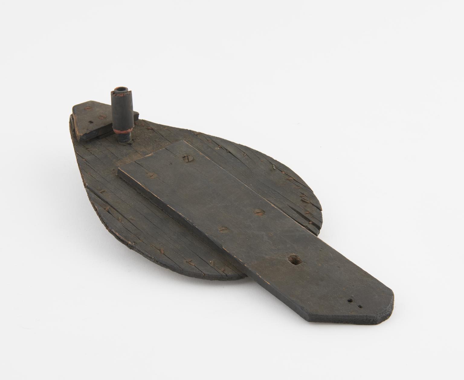
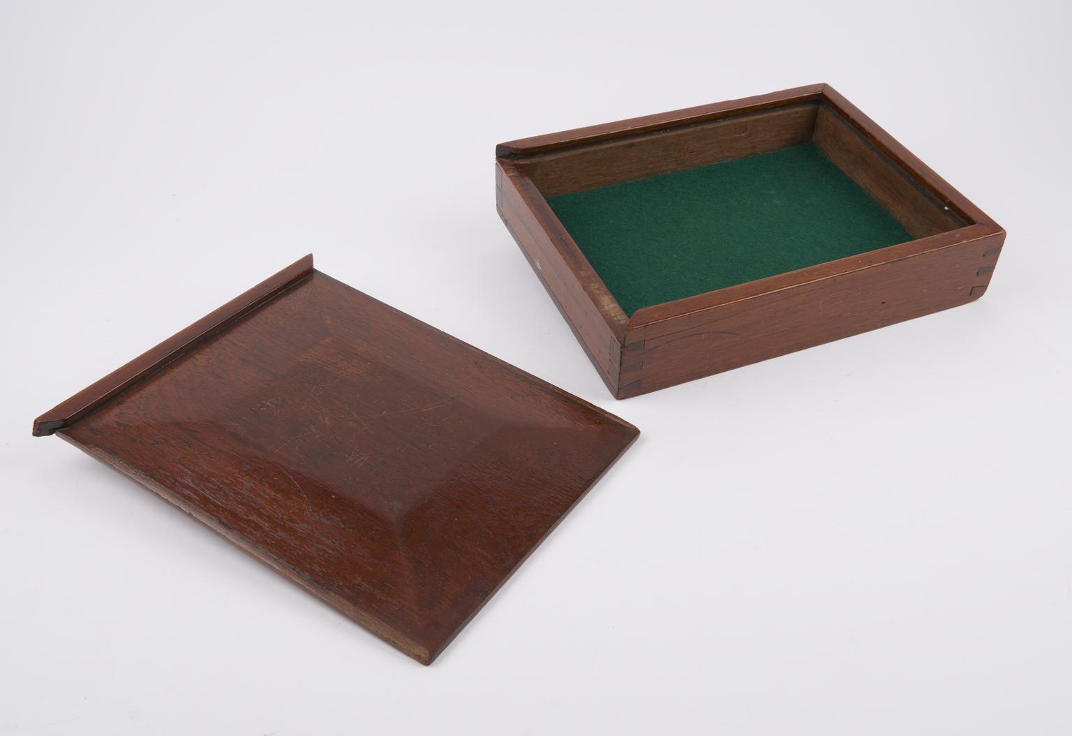
Mahogany box for printing dye, 1821

Mahogany box for printing dye, 1821

Mahogany box for large printing die, used for printing Indian revenue stamps, unsigned, 1821

Object Number:
2008-26/33
type:
box
Image ©
The Board of Trustees of the Science Museum