
Adding No. 6, carrying No. 14. Sketch of a method of adding and carrying intended for a Difference machine. Designed between 31 October 1836 and 12 November 1836. Plan, elevations, details, description.

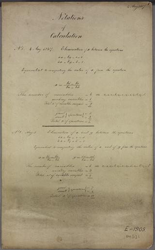
Notation for the coefficients of the powers of x Computation of the coefficients of a polynomial from those of another divided by a linear term.
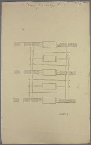
Frame of adding wheels
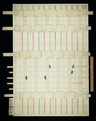
Untitled. This drawing is a cardboard model.
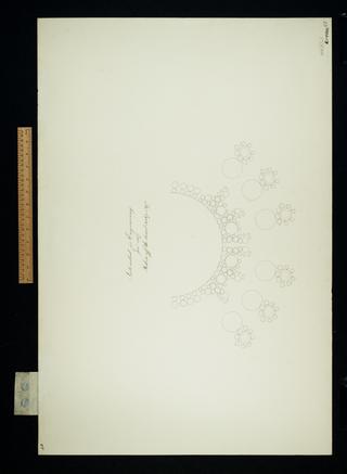
Intended for engraving. Shows six barrels with reducing apparatus.

Addition No. 4. Carriage No 6. Elevation and plan.
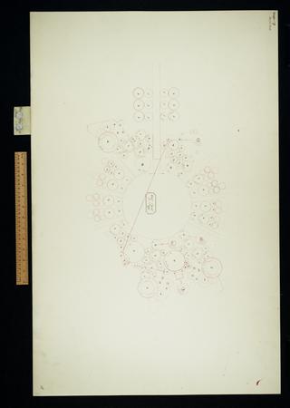
Plan 17, store on a rack. Arrangement.
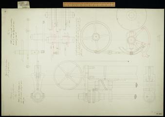
Stepping No. 1 on or in central wheels. Figure 1. Figure 2. Various unnumbered elevations, plans and details.

Sketch 13. General arrangement, circular. Showing 30 variables, 5 barrels with reducing apparatus, punch card mechanism, printing apparatus. Notes introduction of great bevel wheel 18 March 1837.
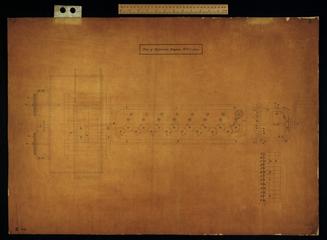
Plan of Difference Engine No. 2. Tracing of BAB A/164.
![Untitled. [Algebraic developments relating to various calculations]](https://coimages.sciencemuseumgroup.org.uk/223/704/large_thumbnail_bab_o_2_0001.jpg)
Untitled. [Algebraic developments relating to various calculations]

See designs dated 1834 November 27 and 1834 December 29.

Sketch of sectors for lifting the axes.

Sketch of the sectors for moving axes of store vertically.

Lifters for selecting the multiple of the Multiplicand or Divisor. Plan, two elevations.
Analytical Engine (appears incomplete).

Gearing et cetera of Sketch dated July 31 1835. Plan, once part of Drawing 22.

No. 1 lifters for the purpose of division by table. Notation and description in sheets 11 and 12 of large quarto notations. Plan, elevation.
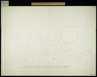
Grouping arrangement. Abandoned end April 1835.

Sketch of wheels for reducing carrying figure wheel axes to zero and setting spiral axes. Sketch elevations.

Sketch No. 5. Two parts each. 1835 July 4. General arrangement.
On putting letters to drawings, in draft.

Method of grouping for the large machine.

Rough draft of Universal Machine Tool. Designed and employed for obtaining the different motions.

Plan and section of an 8 inch figure wheel; hoarding carriage and framing plate. Plan, elevation.

Gearings, et cetera of Sketch No. 8 dated July 31 1835. Arrangement.
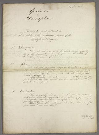
Principles to be followed in the description of the constituent portions of the Analytical Engine.

This plan is entitled 'Carriage 9. Gearing et cetera of Sketch No. 8'

Carriage and method of setting spiral axes for a machine of 50 cages with two figure wheels in each cage. Plan, elevation, details.

Centres of axes and pen sketches of lockings for Sketch 14. Arrangement.
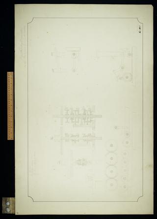
Digit counting apparatus on the two upper wheel selectors.

Sketch of central wheel and principal framing. Plan, elevation.

Carriage with tens warning. Sheet 3.

Figure 1. Clutch et cetera for driving the adding axes. Plan, elevation.

Sketches of mill used for arranging operations on the engine of four wheels in each cage from April 1836 - August 1837.
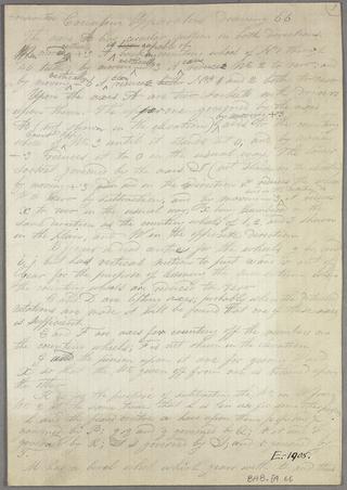
Consecutive counting apparatus.

Rough notes and sketches, including drawings of Babbage's game 'Tit Tat Toe'.

Method of governing barrels et cetera. No. 1, plan of elevation.
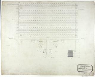
General plan of Analytical Engine, quarter size.

Combinatorial and decimal counting apparatus comprising plan, elevation and description.

Multiplication before the invention of multiplication by table. Sheet 1 of 2.

Sketch of sectors for lifting the axes.
Multiplication before the invention of multiplication by table. Sheet 2 of 2.

Sketch of some of the centres et cetera for Plan 16. Arrangement.

Plan 16. Arrangement, several partial arrangements, numerous notes.

Sketch of a decimal counting apparatus. Plan, elevation, description.
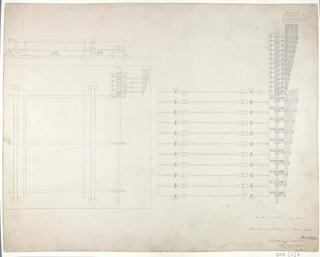
Store variable selectors. Superseding drawing No 2.

Notation of units
