Image
Category
Maker
Object type
Place
Material
Date

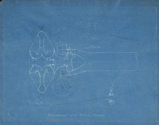
Frank Whittle Jet Engine Blueprints; Three free hand blueprints

[Blueprints (3)] HMS 'Conflict', 'Teazer' & 'Wizard'. Boilers / Maudslay Sons & Field Limtd, Engineers, London. [nd. Scale 1 1/2" : 1']

Blueprints (3) HMS 'Conflict'

nd.

Patent specifications - files containing copies of specifications plus notes, correspondence, drawings. Crabtree and Sons Ltd. Blueprints etc, 1929-30.

Crabtree and Sons Ltd. blueprints, 1929-30

1929-30

Untitled blueprint of a machine. Large pencil drawing used by Morton and subsidiaries, 1922 – 1939.

Untitled blueprint of a machine. Large pencil drawing used by Morton and subsidiaries

1922-1939

'Cam track required if carriages pushed by chain' blueprint. Pencil drawing used by Morton and subsidiaries, 1922 – 1939.

Cam track required if carriages pushed by chain' blueprint. Pencil drawing used by Morton and subsidiaries

1922-1939

‘Shape of carrier and cam track if pulled by chain’ blueprint. Pencil drawing used by Morton and subsidiaries, 1922 – 1939.

‘Shape of carrier and cam track if pulled by chain’ blueprint. Pencil drawing used by Morton and subsidiaries

1922-1939

Untitled blueprint. Pencil drawing used by Morton and subsidiaries, 1922 – 1939.

Untitled blueprint. Pencil drawing used by Morton and subsidiaries

1922-1939

‘Shim bar mechanism’ blueprint, full size. Pencil drawing used by Morton and subsidiaries, 1922 – 1939.

‘Shim bar mechanism’ blueprint

1922-1939

‘Former for Cut Pipe, Terry Pile’ blueprint. Pencil drawing used by Morton and subsidiaries, 19/8/43.

‘Former for Cut Pipe

19th August 1943

‘H’ design. F.N.F. Warp knitting and weft insertion. ‘Sectional End Elevation’ blueprint. Pencil drawing used by Morton and subsidiaries, 28/9/39. Scale: 1/2 full size.

‘Sectional End Elevation’ blueprint

28th September 1939

Relative positions of centres and units for ‘Terry Pile’ and relative positions of centres and units for Cut Pile blueprint. Pencil drawing used by Morton and subsidiaries, 1922 – 1939.

Relative positions of centres and units for ‘Terry Pile’ and Cut Pile blueprint

1922-1939

‘Presser foot arrangement (temporary)’ blueprint. Used by Morton and subsidiaries, 1922 – 1939.

‘Presser foot arrangement (temporary)’ blueprint. Used by Morton and subsidiaries

1922-1939

‘Presser foot arrangements’ blueprint. Used by Morton and subsidiaries, 1922 – 1939.

‘Presser foot arrangements’ blueprint. Used by Morton and subsidiaries

1922-1939

Blueprint fixture for Helice – detailed drawings done at James Templeton + Co. for Caledon/Loom Co. in 1932/3. For mass production of plainfur machine. Used by Morton and subsidiaries, 1922 – 1939.

Blueprint fixture for Helice for mass production of plainfur machine

1922-1939

‘Layout of feed and conveyor mechanism (experimental)’ blueprint. Used by Morton and subsidiaries, 1922 – 1939.

‘Layout of feed and conveyor mechanism (experimental)’ blueprint

1922-1939

‘Fixture for Helice’ blueprint. Used by Morton and subsidiaries, 1922 – 1939.

‘Fixture for Helice’ blueprint. Used by Morton and subsidiaries

1922-1939

[Ship stability calculations re 'Hainaut' and `Pembroke Castle'. 1887. 2 blueprint sheets of calculations re No.155 ship 'Hainaut' and S.S. 'Pembroke Castle'. With accompanying ms. booklets detailing the calculations (using Benjamin's method) re S.S. no.155 'Hainaut' (9 leaves) and T.S.S. no.152 'Bazalgette' (9 leaves). Both booklets bear name 'J. Petree']

Ship stability calculations re 'Hainaut' and `Pembroke Castle'

1887

Timing diagram. Large pencil drawing used by Morton and subsidiaries, 1922 – 1939.

Timing diagram. Large pencil drawing used by Morton and subsidiaries

1922-1939

Plan of Starting Gear. Large pencil drawing used by Morton and subsidiaries, 1922 – 1939.

Plan of Starting Gear. Large pencil drawing used by Morton and subsidiaries

1922-1939

Lingoe Adjuster, 3/8” sq. Brass. 18. OFF. Large pencil drawing used by Morton and subsidiaries, 1922 – 1939.

Lingoe Adjuster line drawing

1922-1939

Untitled blueprint of a machine. Large pencil drawing used by Morton and subsidiaries, 1922 – 1939.

Untitled blueprint of a machine. Large pencil drawing used by Morton and subsidiaries

1922-1939

Details of Cascade M/E. Large pencil drawing used by Morton and subsidiaries, 1922 – 1939.

Details of Cascade M/E. Large pencil drawing used by Morton and subsidiaries

1922-1939

Untitled blueprint of a machine. Large pencil drawing used by Morton and subsidiaries, 1922 – 1939.

Untitled blueprint of a machine. Large pencil drawing used by Morton and subsidiaries

1922-1939

‘Assembly of sinker, sinker blade and brass fitting to hold blades’ blueprint. Pencil drawing used by Morton and subsidiaries, 1922 – 1939.

‘Assembly of sinker

1922-1939

‘Former for 125 Terry Pile and Former for 250 Terry Pile’ blueprint. Pencil drawing used by Morton and subsidiaries, 19th August 1943.

‘Former for 125 Terry Pile and Former for 250 Terry Pile’ blueprint. Pencil drawing used by Morton and subsidiaries

19th August 1943

Untitled blueprint. Pencil drawing used by Morton and subsidiaries, 1922 – 1939.

Untitled blueprint. Pencil drawing used by Morton and subsidiaries

1922-1939

Large blueprint of ‘cascade’. Used by Morton and subsidiaries, 1922 – 1939.

Large blueprint of ‘cascade’. Used by Morton and subsidiaries

1922-1939

‘Weft gearing: - pull carrier’ blueprint. Pencil drawing used by Morton and subsidiaries, 1922 – 1939.

‘Weft gearing: - pull carrier’ blueprint. Pencil drawing used by Morton and subsidiaries

1922-1939

‘Layout of carpet machine mechanism’ blueprint. Pencil drawing used by Morton and subsidiaries, 28/5/46. Scale 2/1.

‘Layout of carpet machine mechanism’ blueprint. Pencil drawing used by Morton and subsidiaries

28th May 1946

‘Needle bar motion’ blueprint. Used by Morton and subsidiaries, 1922 – 1939.

Morton‘Needle bar motion’ blueprint

1922-1939

‘Sewing tension arrangement’ blueprint. Used by Morton and subsidiaries, 1922 – 1939.

‘Sewing tension arrangement’ blueprint. Used by Morton and subsidiaries

1922-1939

‘Spiked beam drive’ blueprint. Used by Morton and subsidiaries, 9/10/33.

‘Spiked beam drive’ blueprint. Used by Morton and subsidiaries

9th October 1933

‘Oscillating arrangement for needle spindles’ blueprint. Used by Morton and subsidiaries, 1922 – 1939.

‘Oscillating arrangement for needle spindles’ blueprint. Used by Morton and subsidiaries

1922-1939

Book of blueprints associated with the German Twin-Gyro vertical stabiliser unit, unmarked, Germany, 1941

Book of blueprints associated with the German Twin-Gyro vertical stabiliser unit

1941

Two blueprints of Agriculture Gallery ironwork designs, c. 1950

Two blueprints of Agriculture Gallery ironwork designs

1950