Image
Category
Collection
Maker
On Display
Object type
Place
Material
Date

Circuit diagram for American transmitter/receiver type RT-66/GRC

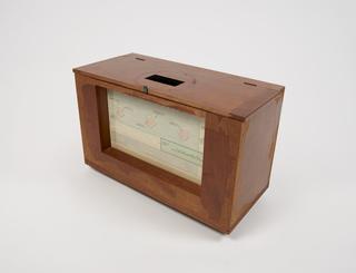
Animated diagram

Diagram for stroboscopic speed regulation
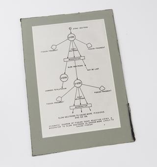
Diagram showing a controlled chain reaction

Wheatstone's harmonic diagram

1821
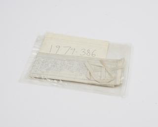
Diagram of an Infundibular Resector in use, 1950

1950

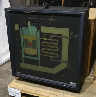
Animated Diagram (Polaroid) of the Dounreay Reactor
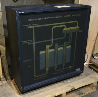
Animated Diagram (Polaroid) of the S.G.H.W. Reactor
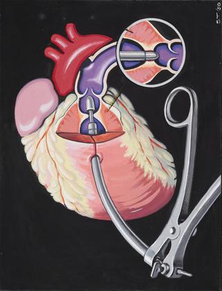
Diagram model of Adelaide rock drill (scale 1.4)

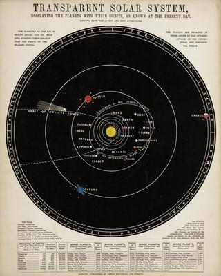
Folder of Astronomical diagrams

1850-1859

Wooden Diagram Model of Joy's Patent radio valve gear
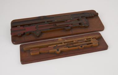
Coloured diagram of Mine Ventilating Furnaces

Coloured diagram of Mine Ventilating Furnaces

Diagram of Schonheyder's water meter

Diagram of Schonheyder's water meter

Diagram of Thomson's method of measuring electromagnet for photo-electrons (1899)

Diagram, method of measuring electromagnet for photo-electrons

1899

Coloured diagram of Guibal Mine Fan, 1867

Coloured diagram of Guibal Mine Fan, 1867

One Diagram - " 'New' Keratometer "

One Diagram - " 'New' Keratometer "

Coloured diagram of Schiele's Mine Fan, 1879

Coloured diagram of Schiele's Mine Fan, 1879

Coloured diagram of Intermittent Pressure Recorder taken from the "White lead engine at the Lead Works" 8.2.1860. In frame 17 1/2" x 4 1/2"

Coloured diagram of Intermittent Pressure Recorder

Perspective diagram of Jonathan Hornblower double cylinder or compound engine, 1781, from Farey "Steam Engine", 1827, Imperial size

Perspective diagram of Jonathan Hornblower double cylinder or compound engine

1827

Large coloured diagram of the potentiometric titration apparatus

Diagram of potentiometric titration apparatus

Diagram showing (in section) construction of Bechhold's ultra filter

Diagram, Bechhold's ultra filter

Coloured diagram showing Steam Circuit of Loeffler Boiler (Model of boiler is on inventory number 1933-548).

Coloured diagram, Steam Circuit of Loeffler Boiler

Three Black line printed diagrams of Pitman's Patent Deflector Regulator for Impulse Water Turbines

Diagrams of Pitman's Patent Deflector Regulator for Impulse Water Turbines

Two sectional diagrams in one frame, of 18, 750 KW Steam Turbine with feed heater and surface condenser as built for Dalmarnoch Power Station, Glasgow, in frame 23 1/4" x 16 1/ 4"

Two sectional diagrams in one frame

Coloured sectional diagram showing a Weir Multi-Stage Turbo Feed Pump, 1938

Coloured sectional diagram showing a Weir Multi-Stage Turbo Feed Pump

Indicator Diagram, dated 19th September 1919, taken on the Watt Pumping Engine of 1777, re-erected at Ocker Hill in 1898 by the Birmingham Canal Navigations

Indicator Diagram

Coloured diagram of calomel electrode, 1927

Coloured diagram of calomel electrode, 1927

1927

Coloured diagram of Lloyd's Centrifugal Fan, 1848

Coloured diagram of Lloyd's Centrifugal Fan, 1848

Coloured sectional diagram of early Heated air pumps

Sectional diagram of early heated air pump

Coloured sectional diagram of Hornblower mine pumping engine, c. 1790

Coloured sectional diagram of Hornblower mine pumping engine

Coloured diagram of Worthington-Davies Compensator for high duty steam pumps, 1885

Coloured diagram of Worthington-Davies Compensator for high duty steam pumps

Coloured diagram of Wilkinson's blowing engine, 1757

Coloured diagram of Wilkinson's blowing engine

Coloured diagram of automatic water distillation apparatus

Diagram of automatic water distillation apparatus

Coloured diagrammatic view, in section, of Boulton and Watt's Rotative Engine, 1788. (Which is on inventory as object number 1861-46).

Coloured diagrammatic view, in section, of Boulton & Watt's Rotative Engine

Coloured diagrams of two rotary drum pumps, 1790 and 1825

Coloured diagrams of two rotary drum pumps

Two diagrams of Cockcroft and Walton's apparatus for the artificial disintegration of the elements by swift protons

Diagrams of Cockcroft and Walton's apparatus

Diagram illustrating the Schichallien experiment for determination of the density of the Earth (1774 - 1776).

Diagram illustrating the Schichallien experiment

Diagram showing the various components of the artificial eye, probably taken from book

Diagram showing the various components of the artificial eye

Diagram of block signalling arrangement for double line working

Diagram of block signalling arrangement for double line working

T/PD type Pressure Corrected Diagram Steam Flow Recorder, framed and glazed table of readings and corrections

T/PD type Pressure Corrected Diagram Steam Flow Recorder

Diagram showing processes and machinery in a flax line spinning mill

Diagram, processes and machinery in flax line spinning mill

Coloured diagram of Trevithick's plunger pole pump, 1797

Coloured diagram of Trevithick's plunger pole pump

Diagram illustrating the method of the reversal of mine ventilation

Illustrative diagram, mine ventilation

Coloured Diagram of Trevithick's Water Pressure Pumping Engine, 1800

Coloured Diagram of Trevithick's Water Pressure Pumping Engine

Coloured sectional diagram showing a Weir Direct-Acting Feed Pump, 1938

Coloured sectional diagram showing a Weir Direct-Acting Feed Pump

Book of hand-drawn technical diagrams - "Bogie Diagrams Part I." Diagrams show outlines of centres of gravity, spring vibrations, oscillation, inclination of links etc. for various types of LMS coach bogie. Contains diagrams XII to XXVIII. Drawings made by Thomas Chidlow in the Divisional Engineer's Office, Derby, c. 1927.

Bogie Diagrams Part 2

circa 1927

Book of hand-drawn technical diagrams - "Bogie Diagrams Part I." Diagrams show outlines of centrifugal forces, gyroscopic action, wheel twist, rail reactions etc. for various types of LMS coach bogie. Contains diagrams 0 to XI. Drawings made by Thomas Chidlow in the Divisional Engineer's Office, Derby, c. 1927.

Bogie Diagrams Part I

circa 1927

Diagram illustrating the process of artificial disintegration of the elements by swift protons

Diagram illustrating the process of artificial disintegration of the elements by swift protons

Animated diagram of oxygen manufacturers

Animated diagram of oxygen manufacturers

Diagram: Apparatus for geothermic investigation.

Diagram: Apparatus for geothermic investigation