Image
Category
Maker
On Display
Object type
Place
Material
Date

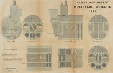
Drawing of multi flue marine steam boiler

1868

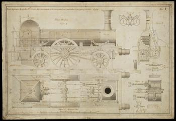
Improvements in the Arrangement & Combination of the Parts of Loco Engine

1841

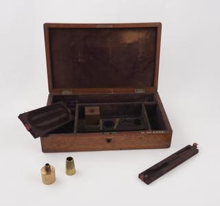
Box for Watt's steam engine indicator and 2 line diagrams

[One of 820 civil and engineering drawings, chiefly of Bramah & Robinson. Drawing no. 1/23: 'Plan and Sections of a Tread Mill, by J. Bramah & Sons, Engineers, Pimlico, proposed for the Gaol at Norwich'. ca.1820. Line drawing with wash. Scale 1" : 4']

Plans and Sections of a Tread Mill ...

circa 1820

Engineering drawing of Blackwall Bridge, Darlington, c. 1832. Ink and wash, scale 1" : 10'. Longitudinal section and cross section of abutment walls. Bridge was "finished 1832 Cost of £2000". Title should probably read Blackwell Bridge.

Blackwall Bridge, Darlington

circa 1832

Line drawing, partly with wash of 38 feet 6 inch bogie composite carriage for S.M. Railway [thought to be Southern Mahratta Railway, India] 2 July 1890, Scale 1" : 1'. Bears 'Tracing No.2713, Drawing No.589' and signature of C.P.Whitcombe, locomotive and carriage superintendent, S.M.Railway.

Southern Mahratta Railway (SMR) 38 feet 6 inch bogie composite carriage

1890-07-02

Drawing, no.16187, longitudinal section and plan of 4-6-4T Horwich-built locomotive

Drawing, no.16187

Drawing, no.16188, smoke box and footplate views and cross sections of 4-6-4T Horwich-built locomotive

Drawing, no.16188

[Engineering drawing] Newcastle-Gateshead Bridge / [Mott, Hay & Anderson, civil engineers, Caxton St.,] Westminster. 1930 Jan. [Colour lithographed, scale 1/4":1'. Drawing No. NG106, cross sections. See also inv. no. 1992-79 (MSP 51)]

Engineering drawing Newcastle-Gateshead Bridge

1930

[Drawing] General arrangement of No.12 Tunnelling Machine / D. Whitaker, Union St, Leicester. [nd. Dyeline, scale 3/4" : 1']

Drawing, General arrangement of No.12 Tunnelling Machine

1901-2000

[Engineering drawing] Turret Mounting for [ship's] 12 inch gun. 1913. [Drawn by V.A.K. Ink and wash, scale 1 : 24]

Turret mounting for 12 inch gun

1913

[Engineering drawing] Plan & Section of two Sets of Pumps for Pumping Water out of Mines [1840? Ink and wash, scale 1/2" : 1'. Bears "Clark Sunderland 1840" in manuscript, and stamp of Great Western Railway Engineer's Office, Paddington and number 31051. Drawing shows Standing Set and Sinking Set. It was one of several lots entered in auction catalogue under group heading "I.K. Brunel's office drawings and sketches of machinery"]

Engineering drawing Plan & Section of two Sets of Pumps for Pumping Water out of Mines

circa 1840

[Engineering drawing] Plunging pump. As used at the Thames Tunnel. 1825 Aug. [Line drawing, scale 1" : 8'. Bears stamp of Great Western Railways Engineer's Office, Paddington and number 31051. It was one of several lots in auction catalogue under group heading "I.K. Brunel's office drawings and sketches of machinery"]

Engineering drawing Plunging pump as used at the Thames Tunnel

1825

Lithograph of 40 Feet Turntable, Battersea Yard, LB&SCR. No 54 in a long running supplement to The Engineer 1869-1881.

40 Feet Turntable. Battersea Yard. LB&SCR

1872-04-12

Lithograph of Goods Engine, Midland Railway. . No 56 in a long running supplement to The Engineer 1869-1881.

Goods Engine. Midland Railway. Mr Matthew Kirtley, Locomotive Superintendent

1872-06-07

Lithograph of Goods Engine, Midland Railway. No 56 in a long running supplement to The Engineer 1869-1881.

Goods Engine. Midland Railway. Mr Matthew Kirtley, Locomotive Superintendent

1872-06-07

Lithograph of L&SWR Company's 7Ft Wheel Coupled Passenger Engine. No 26 in a long running supplement to The Engineer 1869-1881.

L&SWR Company's 7Ft Wheel Coupled Passenger Engine

1869-11-05

Lithograph of Goods Engine, Paris Lyon and Mediterranean Railway. No 117 in a long running supplement to The Engineer 1869-1881.

Goods Engine. Paris Lyon and Mediterranean Railway. M E Marie, Engineer.

1880-01-02

Lithograph of 1st Class Carriage, Western Railway of France. No 118 in a long running supplement to The Engineer 1869-1881.

1st Class Carriage. Western Railway of France.

1880-02-27

Lithograph of Goods Engine, Lancashire and Yorkshire Railway. Constructed to the designs of Mr Barton Wright, Locomotive Superintendent, by the Vulcan Foundry Co, Newton-le-Willows. No 124 in a long running supplement to The Engineer 1869-1881.

Goods Engine... Lancashire and Yorkshire Railway.

1881-12-02

Engineering drawing of London, Tilbury and Southend Railway (LT&SR) 4-coupled bogie tank engine by Thomas Whitelegg, dated 11 March 1907, ink and wash on paper, scale 1" : 1'. Bears stamp of Plaistow Works, No. 1434 and signature of Thomas Whitelegg. He was the LT&SR's Locomotive Carriage, Wagon and Marine Superintendent from 1879 to 1910.

Drawing of London, Tilbury and Southend Railway (LT&SR) 4-coupled bogie tank engine

1907-03-11

Copy engineering drawing of a 18" cylinder goods engine for the East Indian Railway Company, no date.. Line drawing with wash, scale 1 1/2" : 1'. Bears numbers 1960 and No.2.

Drawing of a 18" cylinder goods engine for the East Indian Railway Company

circa 1842-circa 1952

Technical drawing number ‘151472’, described as: ‘MOUNTING BRACKET’, for Met Office exhibition rocket sonde model, dummy, for demonstration, by Bristol Aerojet Ltd., Banwell, Weston-Super-Mare, Somerset, England, 1962-1964

Technical drawing number ‘151472’

1962-1964

Technical drawing number ‘151451’, described as: ‘ARMING PLUG’, and technical drawing number ‘151452’ described as: ‘SAFETY PLUG’, for Met Office exhibition rocket sonde model, dummy, for demonstration, by Bristol Aerojet Ltd., Banwell, Weston-Super-Mare, Somerset, England, 1962-1964

Technical drawing number ‘151451’

1962-1964

Technical drawing number ‘151446’, described as: ‘SWITCH BRACKET’, for Met Office exhibition rocket sonde model, dummy, for demonstration, by Bristol Aerojet Ltd., Banwell, Weston-Super-Mare, Somerset, England, 1962-1964

Technical drawing number ‘151446’

1962-1964

Technical drawing number ‘R.G. 2083’, described as: ‘FIN ATTACHMENT’, for Met Office exhibition rocket sonde model, dummy, for demonstration, by Bristol Aerojet Ltd., Banwell, Weston-Super-Mare, Somerset, England, 1962-1964

Technical drawing number ‘R.G. 2083’

1962-1964

Coloured black line print of drawing, (scale 1:8) of general arrangement of Great Central Railway 4-cylinder 4-6-0 passenger locomotive

Drawing, general arrangement, Great Central Railway 4-6-0 passenger locomotive

Portfolio of Working Drawings, supplements to The Engineer: [12 lithographed locomotive drawings from this long-running supplement series. 1869-1881. See also MSL 91 (inv. no. 1992-99) & MSL 244 (1996-209)]

Portfolio of Working Drawings

1869-1881

Lithographed drawing of Beardmore-caprotti locomotive valve gear

Lithographed drawing of locomotive valve gear

Coloured sectional drawing of Tangye treble barrel plunger pump, 300ft. series

Coloured sectional drawing of Tangye treble barrel plunger pump

Lithograph of Express Passenger Engine, Great Northern Railway. No 47 in a long running supplement to The Engineer 1869-1881.

Express Passenger Engine, Great Northern Railway

1871-06-29

Lithograph of Bogie Tank Locomotive, North Eastern Railway. No 95 in a long running supplement to The Engineer 1869-1881.

Bogie Tank Locomotive. North Eastern Railway. Designed by Mr E Fletcher. Messrs Neilson & Co, Glasgow, Engineers

1876-07-21

Lithograph of Express Passenger Engine, North British Railway. No 106 in a long running supplement to The Engineer 1869-1881.

Express Passenger Engine. North British Railway. Mr D Drummond, Engineer.

1876-07-21

Lithograph of Goods Locomotive for the Bergisch-Mäkische Railway. No 81 in a long running supplement to The Engineer 1869-1881.

Goods Locomotive for the Bergisch-Mäkische Railway. Messrs Henschel & Son, Engineers, Cassell.

1874-12-04

Lithograph of 1st Class Carriage, Western Railway of France, Under Framing. No 119 in a long running supplement to The Engineer 1869-1881.

1st Class Carriage. Western Railway of France. Under framing.

1869-1881

Model (scale 1:8) of Great Northern Railway passenger locomotive, 8ft drivers, 776 class, with sectional drawing of engine and tender, nine negatives, shale ballast and brass half-sectioned cylinder head

Model of Great Northern Railway passenger locomotive

1895-1905

Engineering drawing of the engines of S.S. 'Prometheus' (1886)

Engineering drawing of the engines of S.S. 'Prometheus' (1886)

Section drawing of William Gray's boiler, by William Gray, Hendon, London, England, 1872-1874

Section drawing of William Gray's boiler

1872-1874

Drawings and plans for the Selby diversion of the East Coast Main Line opened in 1983. Includes; 12 bound portfolios of tendering engineering drawings for the Selby Coalfield Diversion of the East Coast Mainline circa 1977-1979, one set of plans submitted with the Act of Parliament for the line. The drawings include alignments of the railway, cross-sections and plans, diversions of roads and footpaths, archaeological sites, as well as detailed drawings of bridges, fences, hedges, drainage, telecommunications. Produced by Chief Civil Engineer's Department, British Rail Eastern Region, Hudson House, York.

Selby Diversion Drawings

1977-1979

Engineering drawing of the Forth Bridge showing sectional elevation of skewbacks showing diaphragms, 188-. Xerox copy, scale 1 : 24.

Forth Bridge, sectional elevation of skewbacks showing diaphragms...

1880-1889

[Engineering drawing] Wearmouth Bridge, Reconstruction. Sunderland / [Mott, Hay & Anderson, civil engineers, Caxton St.,] Westminster. 1930 Jan. Colour lithographed, scale 1/4" : 1'. Drawing No.J70, cross sections

Engineering drawing Wearmouth Bridge

1930

[Engineering drawing] Sydney Harbour Bridge during construction 1930. Dorman Long & Co. Ltd., contractors. [Ink and wash, scale 1:396 (i.e. 1" : 33'). Method of construction shewn, including travelling cranes on superstructure. (Drawn by Science Museum draughtsman)]

Engineering drawing Sydney Harbour Bridge during construction 1930

1930

[Drawing of escapements for clocks] / Richd. Roberts. 1851. [Line drawing with colour wash. Shows 'Detached crank-escapement', 'Detached pin wheel escap[ement]', and one other. Bears name 'Richd. Roberts, Patentee, Globe Works, Manchester'. Relates to patent 12,207 of July 1848?]

Drawing of escapements for clocks

1851

[Engineering drawing: Gates Rock and Ore Breaker / Gates Iron Works, Chicago. Drawn by A.H. Alexander, 11 Nov 1887. Line drawing with wash, scale 3" : 1'. Accompanied by promotional booklet (40p., Dec. 1888 edition), and a sheet (32 x 47cm.) bearing an engraved sectional perspective view and a lengthy ts. explanation. The actual rock and ore breaker, inv. no. 1891-218, was disposed of in ca.1930]

Engineering drawing: Gates Rock and Ore Breaker

1887

[Photo-reproduced line drawing] Pelton Wheel & Patent Oil Pressure Governor / Pitman, Cesar & Co. [ca.1916. The company were turbine manufacturers in Victoria Street, Westminster]

Photo-reproduced line drawing Pelton Wheel & Patent Oil Pressure Governor / Pitman

circa 1916

[Engineering drawing] Plan of Pulverising Mill at Morwelham [nd. Ink and wash, scale 1/4" : 1'. One of a series of lots given the general heading in the auction catalogue of "I.K. Brunel's Office Drawings and Sketches of Machinery"]

Plan of Pulverising Mill at Morwelham

1801-1900

[Copy engineering drawing] Doppeltwirkender Zweitakt-Schiffs-Dieselmotor. Normal-Leistung: 3000 P.S.e. Umdrehungszahl: 120 in der Minute. System Hennig. Patente angemeldet. [Scale 1 : 25. ca.1890-1920]

Copy engineering drawing, Doppeltwirkender Zweitakt-Schiffs-Dieselmotor

1890-1920

[Arrangement drawings (6) of ships Nos. 185 'Branksome Hall', 188 'Trentham Hall', 189 'Childwall Hall' / Harland & Wolff Ltd. 1875-1876. 6 sheets (on roll), line drawings, one with wash. Comprise rigging plan; steering gear; lines; general arrangement drawings]

Ships' technical drawings, for: 'Branksome Hall'; 'Trentham Hall'; and 'Childwall Hall'

1875-1876

[Engineering drawing] Boilers for 1250 HP. 10 pieces. [1 sheet (on roll with others), line drawing, part with wash, 1 3/4 scale]

Engineering drawing Boilers for 1250 HP

1801-1900

Engineering drawing of Switch Capstan, Lever and Crank Box, created by Great Western Railway, Engineers Office. Ink and wask, scale 1 1/2" : 1'. Bears stamp of Great Western Railway Engineers Office, Paddington and 'set' number 30348.

Drawing of Switch Capstan, Lever and Crank Box

1801-1900