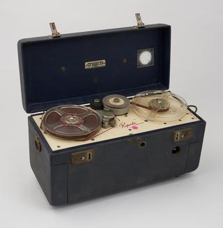
Very early mobile radar receiver type RM1, handmade at Bawdsey in 1937 or 1938
- Made:
- 1937-1938
![]() This image is released under a CC BY-NC-SA 4.0
Licence
This image is released under a CC BY-NC-SA 4.0
Licence
License this image for commercial use at Science and Society Picture Library
License
Science Museum Group Collection
© The Board of Trustees of the Science Museum
Very early mobile radar receiver type RM1, hand-made at Bawdsey in 1937 or 1938, probably early in 1937 around the same time as the type TF3. This mobile radar receiver is one of - if not the - earliest radar receiver in the Science Museum collections. It was described by then Science Museum curator GRM Garratt as "comparatively small but somewhat roughly made."
The design of this receiver was commenced in November 1936 by Mr Dewhurst’s team at the Air Ministry’s experimental station at Orfordness in order to meet an Army requirement in the first instance for a mobile radar station. Following upon the team leader’s initial overall conception, development under his direction proceeded during the spring of 1937 at Bawdsey Research Station; Messrs Willis, Eastwood and Hanbury Brown being respectively responsible for the circuit, phasing and height-curve aspects of the receiver. Field trials were held at Dunkirk during the late summer of 1937.
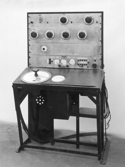
Operating on a wavelength of 13 metres, the equipment was the first in which the height, range and bearing of an aircraft could be determined by direct reading and by a single operator and, in its general layout, it formed a pattern for later forms of mobile radar receivers; notably those of the MRU [Mobile Radar Unit] / TRU [Transportable Radio Unit] installations of which some 300 operated subsequently, particularly in the Middle East and in the North-West Africa, Italian and Normandy landings and in the Western Desert Operations.
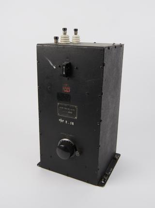
The RM1 receiver was the first to be built at Bawdsey on commercial lines, particularly in its rack system of layout. The top rack contained a transmitter monitor, a receiver monitor and the oscillator. The next rack contained the RF [radio frequency] amplifier in which a novel feature, subsequently adopted in all radar receivers, was the conception of RF valves in push-pull in all the (3) radio frequency amplifier stages. The intermediate frequency amplifier was housed in the next lower rack whilst the metering and switching controls were concentrated in the rack immediately above the operating table.
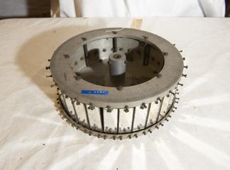
Beneath the table were fitted a loud speaker, receiver power unit, calibrator power unit and the calibrator, with the goniometer and its associated phasing cable-loops immediately below the lefthand side of the operating table, its shaft protruding through into the ‘cake-tin’ above. This cake-tin, later increased in depth (hence the name) to accommodate more elaborate indications of the ‘sense’ quadrants, embodied a map graticule, height curves and sense (i.e. north, south, east or west) quadrants, all surmounting the goniometer; and it permitted, by means of a transparent graduated pointer mounted on the goniometer spindle and operated by a hand knob, successive determinations at sight by the throw of a switch, of map reference and height. It gave thus the first radar ‘plan-position’ presentation, figuring as such in all subsequent MRU [Mobile Radar Unit] / TRU [Transportable Radio Unit] receivers and was in effect a (non-electronic) ‘PPI’ [Plan position indicator] in embryo.
Details
- Category:
- Radio Communication
- Object Number:
- 1948-162
- Measurements:
-
overall: 1770 mm x 1182 mm x 980 mm,
- type:
- radar equipment
- credit:
- Air Ministry