
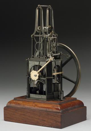
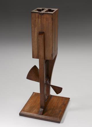
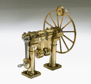
Columnar Engine, 1862
1862
1862

1815

circa 1808

1827
1807
1833-1890
1865-1870

1846
1839-1858
1836
1874-1890
1850-1862
1833-1890
1807
1893

1807
1832
1840
1807
1856-1890
1844-1858
1843
1818-1855
1896
1840-1850
1830-1890
circa 1829
1839
1850-1900
1882
1862-1889
circa 1850
1853