Image
Category
Maker
Object type
Place
Date

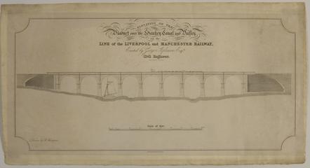
Plan, elevation and brief specification for the Sankey viaduct

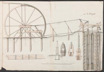
French technical drawings re windmill-

1701-1800

[Large collection of technical drawings of numerous scientific instruments / R.W. Munro Ltd. Late 19th century to 1950s. Basic shelf listing available. See also 1992-804]

Collection of technical drawings of scientici instruments

1957

[French technical drawings re Newcomen atmospheric engine erected at Fresnes, near Conde in northern France, 1737. 3 sheets, ink and colour wash. The engine at Fresnes has "some claim to distinction, as it was chosen by the celebrated architect Bernard Forest de Belidor for illustration and description in his well-known work Architecture Hydraulique (1737)" [H.W. Dickinson, A short history of the steam engine, 1938], after which engravings these three drawings were probably executed. With ink sketch re same, 23 x 16.5cm, and 'Memoire pour l'intelligence de la machine a feu...', 7p. ms., on 2 leaves, each 32 x 40cm folded to 32 x 20cm. With also another ink and colour wash drawing, 33.5 x 26cm, of an unidentified atmospheric engine, slightly different from the Fresnes design]

French technical drawings re Newcomen atmospheric engine erected at Fresnes

1737

[French technical drawings re sluice gates, 17--. 6 sheets, ink and colour wash. Drawings have ms. titles or annotations and detail the construction and workings of sluice-gates]

French technical drawings re sluice gates

1701-1800

[French technical drawings of mill workings. 17--. 2 sheets, ink and colour wash. One drawing is of a powder mill ('moulin a poudre'); one is of a stamping mill (endorsed 'moulin a differentes especes')]

French technical drawings of mill workings

1701-1800

[French technical drawings of parts of the workings of mills. 17--. 3 sheets, ink and colour wash. Drawings, possibly of parts of a portable mill, are accompanied by an 'Explication du moulin portatif', being 1p. ms., on one leaf 22.5 x 33.5 folded to 22.5 x 17cm.]

French technical drawings of parts of the workings of mills

1701-1800

[Portfolio of technical drawings relating to the research work of Leslie E. Sutton, (Oxford Univ. colleague of Prof. Dorothy Hodgkin), recording the development from mid-1930s to mid-1950s of the election diffraction camera he used. ca.120 items]

Portfolio of technical drawings relating to the research work of Leslie E. Sutton

1930-1959

[Technical drawings (3) of 'optical compass' used by C.V. Boys in his recreation of the Cavendish experiment / C.V. Boys. ca.1888. 3 sheets, line drawings with wash; 2 bear ms. annotations; all 3 bear, in pencil, 'Opt. Compass'. No scale]

[Technical drawings (3) of 'optical compass']

circa 1888

[Miscellaneous technical drawings (3) relating to C.V. Boys' recreation of the Cavendish experiment / C.V. Boys. ca.1888. 3 sheets : line drawings, pencil drawing. One bears ms. annotations, one shows plan and side view of dummies and note 'Dummies not used', one shows plan and side elevation of room]

[Miscellaneous technical drawings (3)]

circa 1888

Technical drawings of buildings at stations on particular English railway lines, ca.1835-1902. Comprises ca.250 drawings re London and Birmingham Railway, London and North Western Railway and Lancashire and Yorkshire Railway. Many bear signatures of railway company or contracted engineers.

London & Birmingham Railway, London & North Western Railway, Lancashire & Yorkshire Railway station building drawings

circa 1835-1902

Coloured sectional drawing front and side elevation of Belliss and Morcom Ltd patent self-lubricating Compound Engine

Sectional drawing of Bellis & Morcom Ltd self-lubricating Compound Engine

Coloured sectional drawing (various scales) of Cornish Mine Pump, c. 1840,

Coloured sectional drawing of Cornish Mine Pump

E356/359 and E372, two general arrangement drawings of locomotives for the Caledonian Railway, built by Nielson and Co.

E356/359 and E372

[Drawings (7) of McLaren MP4-7A Formula One racing car / McLaren International. 1992. The chassis itself is in the Museum's Road Transport Collection; 4 associated technical reports are in Archive collection, inv. no. 1997-125 (ref. MS 545)]

Drawings (7) of McLaren MP4-7A Formula One racing car

1992

[8 Dutch technical drawings of windpumps, sluices, screw pumps, lock gates and a lifting bridge / P. Latenstein. ca.1806-1808. See individual entries below]

8 Dutch technical drawings of windpumps

circa 1806-1808

[Technical drawings (6) in ink with colour washes prepared for the French patents covering English specifications 7614 (1838) and 10655 (1845) for the electric telegraph / John Farey for W.F. Cooke and Charles Wheatstone. Scale: various. See also inv. no. 1999-960]

Technical drawings, electric telegraph

1838, 1845

[French technical drawings of a Newcomen atmospheric engine erected at the York Buildings Waterworks on the Thames, 1720s. 2 sheets, ink and colour wash. The larger drawing 'A' depicts a carpentry framed engine after an engraving in Stephen Switzer's An introduction to the general system of Hydrostaticks and Hydraulicks (1729). The detail of the valve-gear, depicted on the smaller drawing, is incorporated as an inset in the engraving. With ink and colour wash drawing 'B', 26.5 x 33.5cm, drawn after the engraving by Sutton Nicholls of 1725 and published in 1726 prior to the completion of the engine for the waterworks which it purports to show. Actually, the general lay-out of the subject has close parallels with Beighton's engraving of a colliery engine at Griff, published in 1717. [Nicholls' adaptation of Beighton's print indicates design improvements between 1717 and 1725]. With also a "Description [re drawing 'B'] d'une machine hidraulique pour Elever l'eau par le moyen du feu"; 16p., ms., on 5 leaves, each 32 x 40cm folded to 32 x20cm. 3 images are on SM b & w neg. and col. trans.]

French technical drawings of a Newcomen atmospheric engine erected at the York Buildings Waterworks on the Thames

1720-1729

Desseins d'une Ecluse sur un Canal traverse par un Courant d'eaux Sauvages ou bourbeues. [17--. 3 sheets, ink and colour wash. Drawings detail lock design and construction]

Desseins d'une Ecluse sur un Canal traverse par un Courant d'eaux Sauvages ou bourbeues

1701-1800

[French technical drawings of sea-walls, sluice gates etc., 17--. 6 sheets, ink and colour wash. Drawings detail the design and construction of sea-walls, sluice gates and the machinery for operating them etc. One drawing is affixed to another producing an overlap]

French technical drawings of sea-walls

1701-1800

[French technical drawings of mills and sluice gates, 17--. 2 sheets, ink and colour wash. Drawings detail the construction and workings of mill wheels and sluice gates. The three drawings on the smaller sheet are duplicated on the larger]

French technical drawings of mills and sluice gates

1701-1800

[French technical drawings, some annotated, of bridge construction, [17--]. 13 sheets, ink or ink and colour wash. Some drawings are ms. annotated. They detail arch construction, drawbridges, piles etc. One shows a pile-driving hammer in action. Bierne and Dunkirk are named. One drawing bears the name Clairac (possibly Louis Andre de La Mamaye Clairac, 1690-1752)]

French technical drawings

1701-1800

[French technical drawings, of a plane table with telescopic alidade, 176-. 5 drawings on 3 sheets, ink and colour wash. Drawings have ms. titles and detail the constituent parts of a plane-table with telescope alidade. With ms. specification (4p in French), and ms. letter, 1766 Sept. 3, Brest to M. Dajot, Douai / Filley, indication that the instrument could be made by Canivet of Paris (4p in French)]

French technical drawings

[French technical drawings etc. re mill workings, 17--. 7 sheets, ink and colour wash/ms. Plans, sections and elevations of machinery equipping various types of mills]

French technical drawings etc. re mill workings

1701-1800

[Drawings (33) re design for an internal combustion turbine / L.M. Lewis. 1942-1945. 7, of 1942, were produced at RAF College, Cranwell; 13 (of 13), of 1945, form a series relating to patent provisional specification 25244]

Drawings (33) re design for an internal combustion turbine

1942-1945

[Collection of BBC Engineering Division technical drawings, 1934-1971, re broadcasting equipment. Comprises 181 A4 files, each containing c.30 drawings. 6 boxes. Listing available]

Collection of BBC Engineering Division technical drawings

1934-1971

[Handbooks and technical drawings, principally wiring diagrams, relating to the installation of the Manchester to Edinburgh television link in the early 1950s. 5 boxes. Listing available] NB: This archive is shortly transferring to NMPFT, Bradford (RS, 9/04)

Handbooks and technical drawings

circa 1951-1955

Coloured sectional drawing scale 1:24 of a Dutch wind driven scoop wheel of the early 18th century

Coloured sectional drawing of a Dutch wind driven scoop wheel

Drawing of Yorkshire Boiler (scale 1:12; details 1:2) made in Museum from information supplied by Messrs. Holdsworth & Sons Ltd., Bradford

Drawing of Yorkshire Boiler (scale 1:12; details 1:2)

Coloured sectional drawing of Hathorn-Davey Rotative Steam Pumping Engine

Coloured sectional drawing of Rotative Steam Pumping Engine

Coloured sectional drawing of a bucket mine pump, 1772, scales 1/120, 1/24, 1/16 and 1/8, 38 1/2"x26"

Coloured sectional drawing of a bucket mine pump

Coloured drawing (scale 1:8), partly in section, of vertical engines used for driving the locomotive shops of the G.E.R. at Norwich, from about 1840 until 1922

Coloured drawing of vertical engines used for locomotive shops of the G.E.R. at Norwich

[Technical drawings (17) prepared for use in the construction of a replica of Charles Babbage's Difference Engine No.1 / R.W. Munro Ltd, London. 1957 Jan-Sept. Ink on oiled linen paper, scales various. See also 1984-407]

Technical drawings

1957

[Dutch technical drawings (8) of various windmills and windpumps / P. Latenstein. ca.1806-1808. See individual part entries below

Dutch technical drawings (8) of various windmills and windpumps

circa 1806-1808