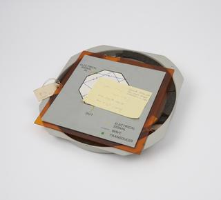
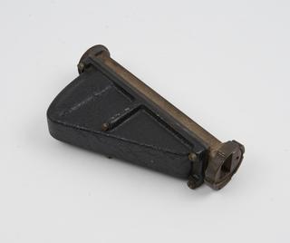
Quartz delay-line for static-target elimination in radar
Decca HD516 radar equipment, display unit, type 4801C
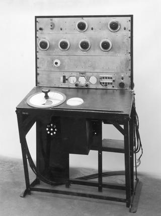
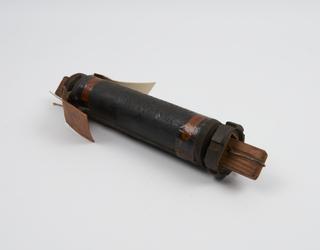
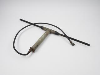
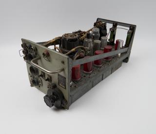
Very early mobile radar receiver type RM1, handmade at Bawdsey in 1937 or 1938
1937-1938
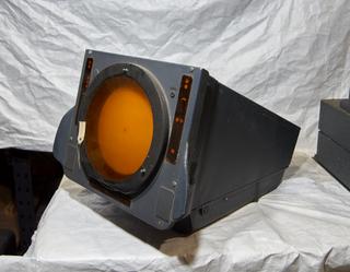
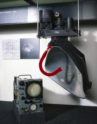
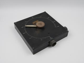
Weather radar indicator
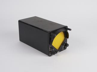
American airborne radar detector, type RT34/APS-13
1939-1945
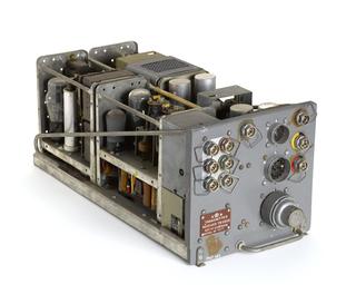
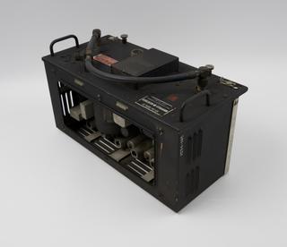
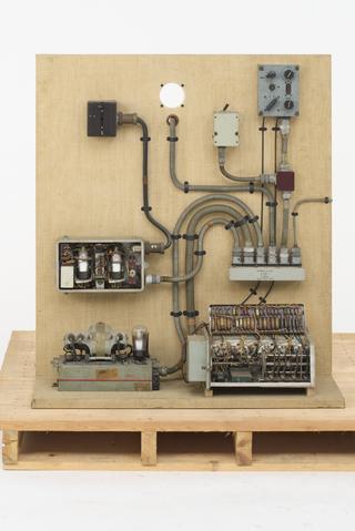
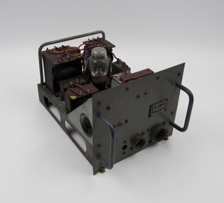
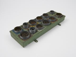
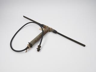
Component of ASV (Air-to-Surface-Vessel radar) Mk.11.N., 1941-1945
1941-1945
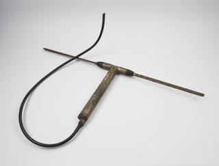
Component of ASV (Air-to-Surface-Vessel radar) Mk.11.N., 1941-1945
1941-1945
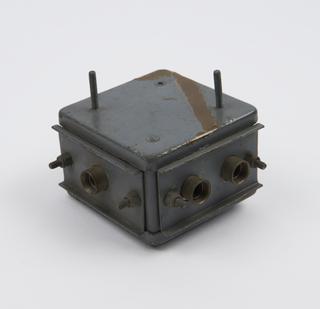
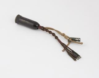
Component of ASV (Air-to-Surface-Vessel radar) Mk.11.N., 1941-1945
1941-1945
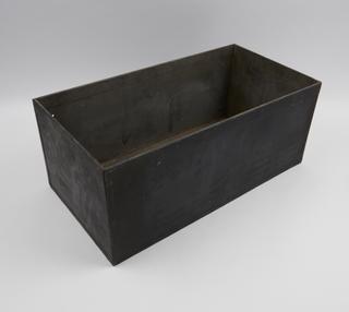
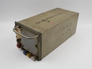
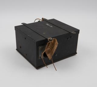
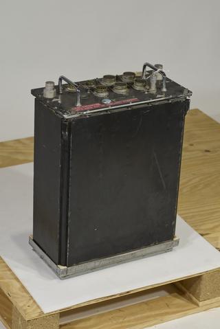
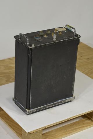
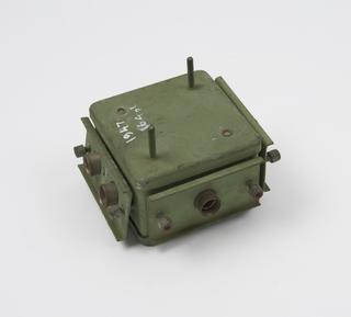
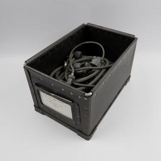
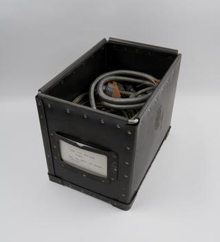
Storage box for radar apparatus used by R.Watson Watt in 1935
1935
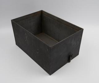
Storage box for radar apparatus used by R. Watson Watt in 1935
1935
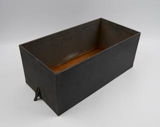
Storage box for radar apparatus used by R.Watson Watt in 1935
1935
Mounted components from Lorenz standard 'blind approach' radar equipment
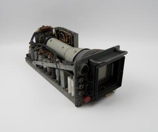
Component from H2S Mk.IIc airborne ground-scanning radar installation, c.1943
1943
Component from H2S Mk.IIc airborne ground-scanning radar installation, c.1943
1943
Component from H2S Mk.IIc airborne ground-scanning radar installation, c.1943
1943
Component from H2S Mk.IIc airborne ground-scanning radar installation, c.1943
1943
Component from H2S Mk.IIc airborne ground-scanning radar installation, c.1943
1943
Component from H2S Mk.IIc airborne ground-scanning radar installation, c.1943
1943
Component from H2S Mk.IIc airborne ground-scanning radar installation, c.1943
1943
Component from H2S Mk.IIc airborne ground-scanning radar installation, c.1943
1943
Component from Lorenz standard 'blind approach' radar equipment
Component from H2S Mk.IIc airborne ground-scanning radar installation, c.1943
1943
Components for Air Intercept (AI) radar Mk. X
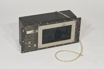
Control/Display Unit for Synthetic Aperture Radar
1989-1990
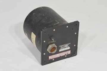
Accellerometer Triaxial Array for Synthetic Aperture Radar
1989-1990
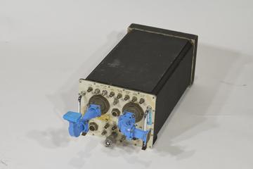
RF Unit for Synthetic Aperture Radar
1989-1990
Power Unit for Synthetic Aperture Radar
1989-1990
Display Store for Synthetic Aperture Radar
1989-1990
Component of air-to-surface-vessel (ASV) Mk XI radar equipment
Component of air-to-surface-vessel (ASV) Mk XI radar equipment
Component of air-to-surface-vessel (ASV) Mk XI radar equipment
Component of air-to-surface-vessel (ASV) Mk XI radar equipment
Component of air-to-surface-vessel (ASV) Mk XI radar equipment
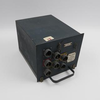
Component of ASV (Air-to-Surface-Vessel radar) Mk.11.N., 1941-1945
1941-1945
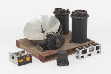
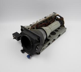
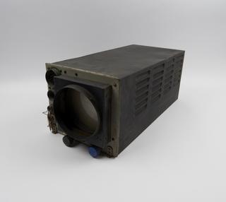
Scanner for H2S Mk.IIc airborne ground-scanning radar installation, c.1943
1943
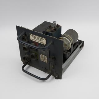
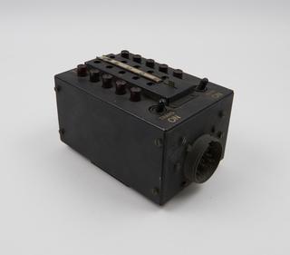
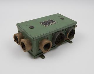
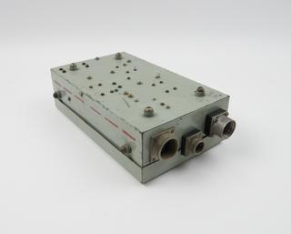
Voltage Control Panel Type 3 of ASV (Air-to-Surface-Vessel radar) Mk.11.N., 1941-1945
1941-1945
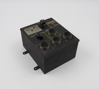
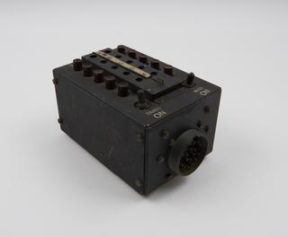
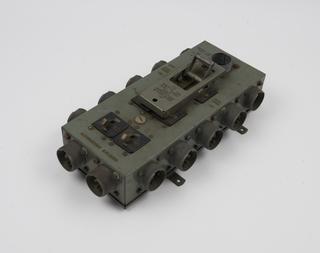
Control Panel Type 6 of ASV (Air-to-Surface-Vessel radar) Mk.11.N.
1941-1945
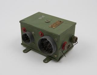
Component of ASV (Air-to-Surface-Vessel radar) Mk.11.N., 1941-1945
1941-1945
Component of ASV (Air-to-Surface-Vessel radar) Mk.11.N., 1941-1945
1941-1945
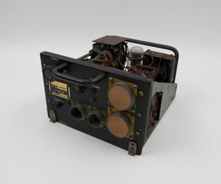
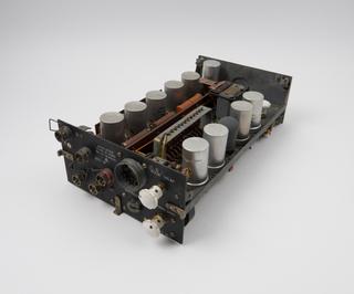
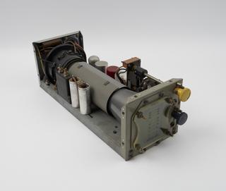
Receiver Type 3132B of ASV (Air-to-Surface-Vessel radar) Mk.11.N., 1941-1945
1941-1945
ASV (air-to-surface vessel) Mk XI radar scanner
Component of air-to-surface-vessel (ASV) Mk XI radar equipment
Component of air-to-surface-vessel (ASV) Mk XI radar equipment
Component of ASV (Air-to-Surface-Vessel radar) Mk.11.N., 1941-1945
1941-1945
Component of ASV (Air-to-Surface-Vessel radar) Mk.11.N., 1941-1945
1941-1945
Display unit (0-100) of ASV (Air-to-Surface-Vessel radar) Mk.11.N., 1941-1945
1941-1945
Component from Lorenz standard 'blind approach' radar equipment
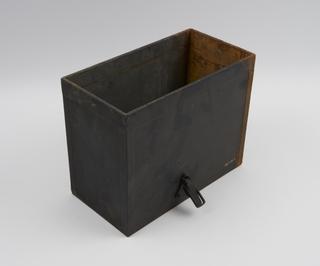
Storage box for radar apparatus used by R.Watson Watt in 1935
1935
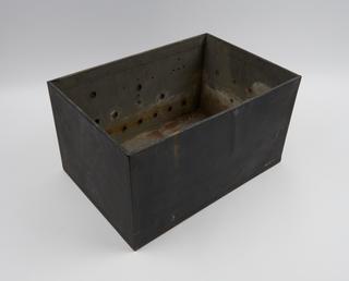
Storage box for radar apparatus used by R.Watson Watt in 1935
1935